

Description
- Brand: ABB
- Full Model Number: UNITROL 1000 3BHE014557R0104
- Internal Board Identification: 3BHE006720R0001
- Serial Identification: 289942
- Lifecycle Status: Legacy UNITROL 1000 generation; current ABB documentation is centered on newer UNITROL 1010/1020 versions
- Core Function in System: Automatic voltage regulation and excitation control for indirectly excited synchronous generators and synchronous motors
- Top 3 Hardcore Specs: Up to 15 A exciter current; wide input-voltage/frequency range; microprocessor + IGBT control
- Control Functions: AVR, reactive-power control, power-factor control, field-current regulation
- Interface: Local front-panel display and controls
- Mounting: Compact cabinet/panel installation
- Condition & Lead Time: Replacement availability subject to serial/firmware/hardware verification; emergency dispatch based on confirmed inventory
ABB’s UNITROL 1000 manual describes the controller as an automatic voltage regulator for indirectly excited synchronous machines, with the ability to operate as a reactive-power, power-factor, or field-current regulator. The same manual states that the platform is intended for synchronous generators and motors with exciter current up to 15 A.
For the exact commercial identification supplied here, 3BHE014557R0104 is associated with the UNITROL 1000 assembly, while 3BHE006720R0001 is identified as its internal board number and 289942 as the serial number in available records.
Module 3: Technical Intro & Downtime Impact
A generator can remain mechanically available yet fail to build or regulate terminal voltage when its excitation controller is unavailable. ABB UNITROL 1000, 3BHE014557R0104, is an automatic voltage regulator for synchronous machines. Its control function extends beyond simple voltage regulation: the documented platform can be switched to reactive-power, power-factor, or field-current regulation. That makes the controller a critical part of the excitation chain, not a convenience device.
For MTTR planning, the most useful fixed data are the 15 A exciter-current capability, broad input-voltage and operating-frequency range, and microprocessor/IGBT architecture documented by ABB. The current ABB UNITROL 1000 family documentation provides a dedicated commissioning tool and parameter-management workflow, while newer UNITROL 1010/1020 documentation exposes USB, Ethernet, CAN, and Modbus capabilities on the current generation. Do not transfer those newer interface specifications to this older 3BHE014557R0104 assembly without verification. —The exact firmware revision, configuration file, internal board revision, and machine-specific settings should be checked before replacement.
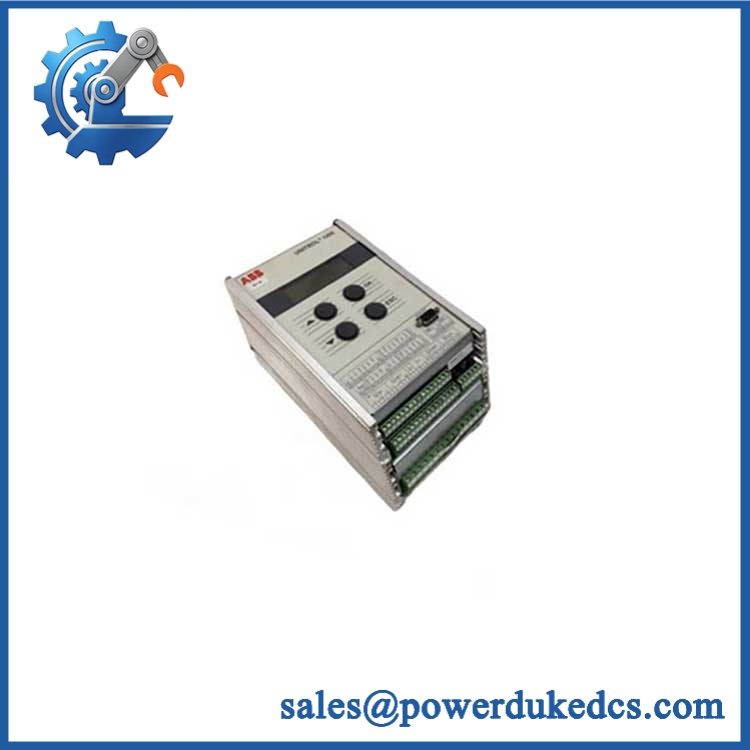
ABB UNITROL1000 3BHE014557R0104
Module 4: Dynamic Emergency Swap & Configuration Guide
1. Pre-Swap Prep — Freeze the excitation configuration
- Place the generator/motor excitation system in the approved maintenance condition.
- Follow the machine’s electrical isolation and lockout procedure.
- Verify field-circuit and auxiliary-supply isolation before opening the regulator enclosure.
- Record the exact 3BHE014557R0104 identification, internal board number 3BHE006720R0001, serial number, and firmware revision.
- Back up the UNITROL 1000 parameter set using the approved ABB configuration procedure.
- Photograph the front panel, terminal wiring, communication connections, and any configuration labels.
- Use ESD controls when handling the controller.
2. Removal — Preserve every connection
- Confirm absence of hazardous voltage at the controller and associated excitation circuits.
- Label each terminal conductor before disconnecting it.
- Document the wiring associated with generator voltage, current, field-current feedback, auxiliary supply, and control inputs.
- Disconnect external communication or service connections.
- Release the controller’s cabinet/panel retaining hardware.
- Remove the UNITROL 1000 without stressing terminal blocks or internal PCB connections.
- Inspect the surrounding wiring for heat damage, loose terminals, or insulation deterioration.
3. Installation & Configuration — Restore the machine-specific setup
- Verify UNITROL 1000 / 3BHE014557R0104 and the internal 3BHE006720R0001 identification.
- Compare hardware revision and firmware against the failed controller’s recorded data.
- Install the replacement in the original mechanical position.
- Reconnect every terminal according to the documented wiring record and approved ABB drawing.
- Restore the backed-up parameter set rather than relying on default settings.
- Verify voltage sensing, field-current measurement, control mode, limiters, and protection thresholds.
- Confirm regulator communication settings where applicable.
- Do not assume a newer UNITROL 1010/1020 configuration is interchangeable with this older UNITROL 1000 assembly.
4. Power-On Self-Test (POST) — Validate regulation before load
- Re-energize the regulator according to the approved commissioning sequence.
- Check the local display for normal startup and absence of persistent fault indications.
- Confirm the controller recognizes the connected measurement inputs.
- Verify generator voltage feedback and field-current feedback.
- Test AVR operation at the permitted commissioning condition.
- Check reactive-power, power-factor, or field-current control only if those functions are used by the machine.
- Verify limiter and protection behavior before applying normal operating conditions.
- Record final measured values against the pre-failure baseline.
ABB’s older UNITROL 1000 documentation specifically identifies a local operator panel and software-assisted commissioning. The exact startup display sequence and parameter locations depend on the installed software revision, so the failed unit’s recorded firmware/configuration should remain the reference during an emergency replacement.
Module 5: Quality Assurance & Testing SOP
A UNITROL 1000 replacement should be treated as a configured excitation controller. Identity alone is insufficient; the test record should establish hardware condition, configuration compatibility, and regulation behavior.
1. OEM identity verification
- Verify ABB
- Verify UNITROL 1000
- Verify 3BHE014557R0104
- Verify internal board 3BHE006720R0001
- Record serial identification where present, including 289942 when applicable
- Compare nameplate, front-panel layout, connectors, terminal markings, and hardware revision
- Perform OEM anti-counterfeit visual inspection
- Photograph all identification markings
2. Physical inspection
- Inspect the enclosure for impact damage, corrosion, contamination, and deformation
- Check terminal blocks for cracks or damaged retaining hardware
- Inspect connectors and communication interfaces
- Check cooling passages and ventilation surfaces for blockage
- Inspect PCB areas for discoloration, damaged components, cracked solder joints, or evidence of unauthorized rework
- Record physical condition before energization
3. Electrical screening
- Verify supply-path continuity according to the approved test method
- Check protective earth continuity where applicable
- Inspect terminal integrity and connector pin condition
- Perform insulation testing only where specifically permitted by the UNITROL design and with sensitive electronics isolated
- Do not apply arbitrary hipot voltages directly across populated regulator electronics
4. Functional testing
- Apply the approved controller supply in a controlled test environment
- Perform power-on self-test
- Check display initialization and applicable fault/status indications
- Verify voltage measurement inputs
- Verify field-current measurement
- Verify digital control inputs and outputs where fitted
- Simulate the regulation reference and confirm controller response
- Test AVR response under controlled conditions
- Verify applicable reactive-power, power-factor, and field-current functions
- Confirm limiters and protective functions within the approved test envelope
- Record firmware revision, parameter set, measurements, and test results
5. Final QC release
- Independent QC sign-off
- Parameter backup retained with the test record
- ESD-safe and mechanically protected packaging
- Terminal and connector protection
- Final cross-check of 3BHE014557R0104 / 3BHE006720R0001
- Shipment released only after identity and functional records are complete
ABB’s UNITROL 1000 manual states that the controller is intended for trained personnel and provides installation, commissioning, operation, and settings information. ABB also maintains dedicated commissioning instructions and control-software documentation for the UNITROL 1000 family.
Module 6: Maintenance & Reliability FAQ
Q1. Is ABB UNITROL 1000 3BHE014557R0104 a direct drop-in replacement, or does it require a firmware flash?
Do not treat it as a blind drop-in replacement. Match 3BHE014557R0104, internal board 3BHE006720R0001, hardware revision, firmware revision, and the machine-specific parameter set. A firmware change should be performed only when the applicable ABB documentation identifies a required revision. The UNITROL 1000 is a configurable excitation regulator, so preserving the original settings is as important as matching the hardware.
Q2. Is it safe to hot-swap the UNITROL 1000 while the generator is running?
Do not assume hot-swap capability. The regulator is connected to generator measurements, auxiliary power, control circuits, and the excitation chain. Replacement should be performed under the machine-specific isolation and commissioning procedure unless the exact installation has a documented live-maintenance method.
Q3. Will replacing the UNITROL 1000 cause my current program or configuration to be lost?
The safest approach is to back up the complete parameter set before removal and record the firmware revision and critical settings. Pay particular attention to voltage sensing, field-current scaling, control mode, limiters, protection thresholds, and external control inputs. After installation, restore the documented configuration and compare the measured response with the pre-failure baseline.
Q4. What is the maximum exciter current associated with this UNITROL 1000 platform?
ABB’s UNITROL 1000 manual identifies the product as a compact AVR for synchronous machines up to 15 A exciter current. Actual permissible operating current still depends on the specific regulator configuration, excitation system, and installation conditions.
Q5. What should I verify before ordering a replacement?
Verify the complete UNITROL 1000 3BHE014557R0104 identification, internal board number 3BHE006720R0001, serial number where available, hardware revision, firmware revision, machine application, terminal configuration, and backed-up parameter set. Do not substitute specifications from the current UNITROL 1010/1020 generation merely because the product family name is similar. ABB’s current 1000-series documentation now distinguishes 1010 and 1020 hardware with their own electrical ratings and interfaces.











 Start Chat


