

Description
- Brand: ABB
- Full Model Number: UNS0007A-P,V1
- ABB Product ID: HIEE305098R0001
- Product Type: Firing Board
- Rated Voltage: 1400 V
- Product Family: UNITROL P excitation system
- Core Function in System: Thyristor firing control within the generator excitation system
- Application: UNITROL P static excitation equipment
- Board Construction: Electronic firing/interface PCB
- Origin Listed in Product Record: Switzerland
- Net Dimensions: 245 × 142 × 190 mm
- Net Weight: 0.51 kg
- Customs Classification Listed: 85372000
- Condition & Lead Time: Stock condition subject to inspection; emergency dispatch available subject to order confirmation
ABB’s product identification data lists HIEE305098R0001 as UNS 0007A-P,V1: Firing Board 1400V. The same identification is independently reported for the ABB UNITROL P excitation-system firing board.
Identification note: the user-supplied identifier is HIEE305098R0001; the corresponding ABB designation reported in product records is UNS 0007A-P,V1. Do not substitute the unrelated UNC4673A measuring-interface board from the same UNITROL P family.
Module 3: Technical Intro & Downtime Impact
A firing-board failure can stop a generator excitation system at the point where control commands must be converted into correctly timed thyristor firing signals. The generator may still be mechanically available, yet excitation cannot be established or regulated correctly. ABB UNS0007A-P,V1 / HIEE305098R0001 is identified as a 1400 V firing board for UNITROL P excitation equipment. That places it directly in the excitation firing path, where an incorrect replacement can prevent startup or create persistent excitation-system faults.
For MTTR, exact part-number and voltage-class matching are the first controls. The product record identifies 1400 V service, with a reported physical size of 245 × 142 × 190 mm and 0.51 kg net weight.I did not find a sufficiently authoritative ABB technical document establishing this board’s exact gate-pulse timing, firing-current limits, auxiliary supply, insulation test values, or board-level MTBF. Those parameters should therefore be taken from the specific UNITROL P schematic and firing-system documentation for the installed excitation cabinet. (Do not infer gate-drive settings from another UNS or UNC board.)
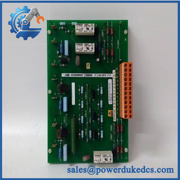
- ABB UNS0007A-P V1 HIEE305098R0001
Module 4: Dynamic Emergency Swap & Configuration Guide
1. Pre-Swap Prep — Capture the Excitation Firing Configuration
Place the generator excitation system in the plant’s approved maintenance state and isolate all relevant excitation and auxiliary power sources. Verify the absence of hazardous voltage before opening the cabinet. Record UNS0007A-P,V1 / HIEE305098R0001, board revision, rack or chassis position, connector identities, firing-channel assignments, thyristor-bridge configuration, and fault history. Photograph the existing board and every cable connection.
2. Removal — Extract the Firing Board Without Disturbing Gate Wiring
This is an internal UNITROL P firing board, not a DIN-rail or field-mounted device. After isolation and verification of safe conditions, disconnect the board’s control, firing, feedback, and auxiliary connections according to the cabinet drawing. Release the board-retention hardware and withdraw it straight from the mating interface.
Keep all gate/firing conductors identified by channel. Do not swap connector positions during removal; a wiring error on a thyristor firing path can produce a completely different fault from the original board failure.
3. Installation & Configuration — Match the 1400 V Board Exactly
Verify UNS0007A-P,V1 and on the replacement before installation. The available product identification explicitly defines this combination as a 1400 V firing board.
Install the board in the original position and restore every connector against the excitation-system wiring diagram. Preserve the original firing-channel order and any board-specific jumpers, links, or calibration settings. Do not substitute another UNITROL P circuit board based on physical similarity: ABB’s UNITROL P spare-parts documentation distinguishes firing interfaces from measurement interfaces, and the UNC4673A family serves a different function.
4. Power-On Self-Test (POST) — Prove Firing Synchronization Before Excitation
Restore auxiliary power under the controlled commissioning procedure and inspect the UNITROL P diagnostic state. Verify that the firing board produces no hardware or synchronization faults.
Before applying field excitation to the generator, perform a controlled firing-system test using the approved UNITROL P test procedure. Confirm correct channel sequencing, synchronization with the applicable bridge reference, gate-signal presence, and diagnostic feedback. Only after the firing path passes should a controlled excitation enable test be performed. (A board that powers up without an alarm can still have a channel-specific firing defect.)
Module 5: Quality Assurance & Testing SOP
Each ABB UNS0007A-P,V1 / should undergo strict board inspection and a controlled UNITROL P firing test before shipment.
- OEM anti-counterfeit visual inspection: Verify ABB markings, designation, V1 revision, identification, PCB layout, connector construction, component population, and manufacturing quality.
- Exact part-number verification: Confirm and against the physical board and inventory record.
- Mechanical inspection: Check PCB edges, mounting points, connectors, terminal interfaces, contamination, corrosion, cracked solder joints, burned components, and evidence of unauthorized repair.
- Voltage-class verification: Confirm the board is specifically identified as the 1400 V firing-board version.
- Power-on self-test (POST): Install the board in an approved compatible UNITROL P test assembly and verify startup diagnostics and system status.
- Interface continuity test: Verify accessible low-voltage control and firing-interface paths against the approved schematic before enabling the high-energy firing circuit.
- Gate-pulse simulation: Use an approved firing-board test fixture to verify the timing and presence of the required firing outputs for the supported bridge configuration.
- Channel-by-channel firing test: Exercise each applicable thyristor firing channel independently and record the measured pulse response.
- Synchronization test: Verify that firing commands remain synchronized with the applicable AC reference throughout the permitted test range.
- Feedback/diagnostic test: Confirm expected firing-status feedback and diagnostic behavior at the UNITROL P controller.
- I/O full-range simulation: Exercise applicable control, synchronization, inhibit, enable, and diagnostic signals using the approved laboratory fixture.
- Fault simulation: Introduce controlled loss-of-reference, inhibit, or channel-fault conditions where the test procedure permits and verify the expected diagnostic response.
- Thermal observation: Monitor the board during representative operation for abnormal temperature rise, intermittent behavior, or localized component heating.
- Extended stability test: Repeat firing cycles while monitoring for pulse loss, synchronization drift, resets, or intermittent channel faults.
- Final QC record: Document part number, revision, voltage class, host UNITROL P configuration, firing channels tested, measured timing/results, diagnostic behavior, test duration, photographs, technician sign-off, and packaging condition.
Module 6: Maintenance & Reliability FAQ
1. Is ABB ,V1 a direct drop-in replacement, or does it require a firmware flash?
The available product identification classifies / ,V1 as a 1400 V firing board, not as a CPU or general-purpose controller.A firmware flash is therefore not normally the defining replacement task. The critical checks are the exact board identity, revision, firing-channel configuration, host UNITROL P hardware, and any board-specific calibration or link settings.
2. Is it safe to hot-swap ,V1 while the excitation system is running?
No. A firing board interfaces with the excitation power stage and thyristor control circuitry. The associated circuits can contain hazardous voltage and stored energy. Isolate the excitation system and verify safe conditions before removing the board under the approved plant procedure.
3. Will replacing ,V1 cause my current program or excitation settings to be lost?
The firing board itself is not the primary application-memory controller. Replacing it should not normally erase the main UNITROL P control program. The critical risk is retaining the existing firing-channel configuration, calibration information, jumper/link positions, and controller parameters. Record those values before removal and retain the original board until commissioning is complete.
4. What should I verify before commissioning the replacement?
Verify , , the 1400 V rating, board revision, UNITROL P cabinet type, connector positions, firing-channel assignment, and associated thyristor bridge. The product record also identifies the board as approximately 0.51 kg with 245 × 142 × 190 mm dimensions.Then perform a controlled gate-firing and synchronization test before applying production excitation.
5. What are the warranty terms if the unit fails after installation?
Warranty coverage should be stated on the quotation or sales order for the specific serialized board. Retain the incoming inspection report, board photographs, revision identification, pre-replacement firing diagnostics, channel-by-channel test results, and commissioning records. For excitation firing hardware, this documentation helps distinguish a board fault from thyristor-bridge issues, fiing-cable faults, synchronization-reference problems, or controller configuration errors.











 Start Chat


