

Description
- Brand: ABB
- Full Model Number: UNS0861A-P V2
- ABB Part Number: HIEE305084R0002
- Product Family: UNITROL F
- Product Type: Excitation-System Power Supply
- Lifecycle Status: Legacy UNITROL F installed-base component
- Core Function in System: Supplies operating power to the UNITROL F excitation-control system and associated electronics
- Top 3 Hardcore Specs: 110–220 V input supply; UNITROL F excitation-system application; V2 hardware revision
- Input Supply: 110–220 V
- Primary System: Generator excitation control
- Version: V2
- Condition & Lead Time: Tested inventory or factory-sealed stock; emergency dispatch subject to confirmed availability
ABB’s own UNITROL F spare-parts documentation identifies HIEE305084R0002 as UNS 0861 A-P V2, with the description Power Supply 110–220 V. The same ABB document distinguishes V1, HIEE305084R0001, as the 24–48 V version.
Module 3: Technical Intro & Downtime Impact
A failed excitation-system power supply can take an otherwise healthy generator control system offline. When the controller, measurement circuits, and auxiliary electronics lose their required supply rails, troubleshooting can quickly expand into a system-level outage. ABB UNS0861A-P V2 HIEE305084R0002 is the UNITROL F power-supply version specified for 110–220 V input, so exact voltage-variant matching is the first replacement check.
The V1/V2 distinction is not cosmetic. ABB identifies HIEE305084R0001 as the 24–48 V version and HIEE305084R0002 as the 110–220 V version. Using the wrong supply variant can prevent startup or create an unsafe mismatch with the plant’s auxiliary power architecture. Public non-OEM listings also describe this unit as a UNITROL F power supply, but ABB’s own identification should govern procurement and commissioning decisions. —especially important on generator systems where an excitation restart can become the limiting path to unit availability.
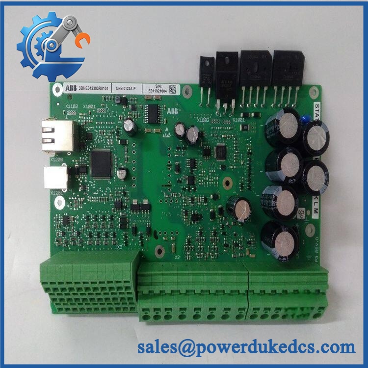
ABB UNS0861A-P,V2 HIEE305084R0002
Module 4: Dynamic Emergency Swap & Configuration Guide
1. Pre-Swap Prep — verify the supply variant before opening the cabinet
Place the UNITROL F excitation system in the plant-approved maintenance state and complete the required LOTO procedure. Verify the absence of hazardous voltage using properly rated test equipment. Photograph the existing UNS0861A-P V2 nameplate, wiring, connectors, terminal positions, LED condition, and mounting location. Confirm the incoming supply is within the documented 110–220 V class and record any system-specific fuse, jumper, or configuration information. ABB distinguishes this V2 unit from the 24–48 V V1 version.
2. Removal — preserve the original power connections
After isolation and voltage verification, label every power and control connection. Record connector positions against the cabinet schematic. Release the power-supply assembly from its mechanical mounting and remove it without stressing adjacent boards or wiring. Inspect terminals, connectors, fuses, and neighboring excitation electronics for overheating, arcing, corrosion, or insulation damage. A failed supply may have been caused by a downstream fault, so do not install the spare before the original failure path has been checked.
3. Installation & Configuration — match the 110–220 V architecture
Install the replacement HIEE305084R0002 in the original position and reconnect every interface according to the approved UNITROL F drawing. Confirm input wiring polarity and phase/neutral arrangement where applicable. Verify the system is designed for the 110–220 V V2 supply variant before energization. Do not substitute HIEE305084R0001 simply because it carries the same UNS0861A-P family designation; ABB specifies the two versions for different input-voltage classes.
4. Power-On Self-Test (POST) — prove every downstream supply function
Energize the supply under the approved commissioning sequence and observe all available power and fault indicators. Confirm expected output rails, controller startup, and communication with the UNITROL F control system. Check excitation-system diagnostics for undervoltage, supply, or controller faults. Then verify measurement, control, and auxiliary modules downstream of the power supply before allowing the generator to proceed through the normal excitation startup sequence.
Module 5: Quality Assurance & Testing SOP
The UNS0861A-P V2 should be tested as a critical excitation-system power component.
- OEM Anti-Counterfeit Visual Inspection: Verify ABB markings, UNS0861A-P V2, and HIEE305084R0002 identification against verified reference documentation.
- Serial and Identity Traceability: Photograph the complete nameplate and record serial number, revision, and visible manufacturing identifiers.
- Mechanical Inspection: Check mounting points, enclosure, terminal blocks, connectors, PCB edges, and retention hardware.
- Input Voltage Verification: Confirm the test setup is suitable for the documented 110–220 V supply class.
- Power-On Self-Test (POST): Apply controlled input power and record startup behavior and all available status/fault indications.
- Output-Rail Verification: Measure every accessible output rail under no-load and representative-load conditions according to the applicable UNITROL F documentation.
- Load Test: Apply a controlled representative load and monitor output stability, current, and voltage during startup and steady operation.
- Protection Test: Where supported by the test setup, verify overvoltage, overcurrent, short-circuit, and related protection behavior against the applicable technical specification.
- Controller Startup Test: Confirm that the connected UNITROL F control hardware initializes normally from the replacement supply.
- Communication/Status Test: Verify downstream controller diagnostics and system status after supply restoration.
- Thermal Observation: Monitor the supply during an extended powered run for abnormal heating, intermittent shutdown, or output drift.
- Failure-Recovery Test: Where laboratory procedures permit, cycle input power and verify repeatable startup without abnormal diagnostic states.
- Final QC Record: Document part number, supply variant, measured input/output values, serial traceability, test duration, photographs, and QC approval.
ABB’s spare-parts documentation specifically defines as the 110–220 V power-supply version for UNITROL F, which should be the primary reference for incoming inspection and procurement verification.
Module 6: Maintenance & Reliability FAQ
1. Is the V2 a direct drop-in replacement, or does it require a firmware flash?
This is a power-supply assembly, not the main application controller, so a firmware flash is not normally the principal replacement task. The critical compatibility check is the input-voltage variant. ABB identifies specifically as UNS 0861 A-P V2, Power Supply 110–220 V.
2. Is it safe to hot-swap this power supply while the system is running?
Do not assume live replacement is permitted. This unit belongs to a generator excitation system and is connected to potentially hazardous supply circuits. Unless the exact UNITROL F installation documentation explicitly authorizes energized replacement, isolate the system and verify absence of hazardous voltage before removal.
3. Will replacing this power supply cause my current excitation program to be lost?
Replacing the power supply does not itself constitute replacement of the excitation application. Nevertheless, preserve the controller configuration, excitation parameters, communication settings, and diagnostic records before intervention. If the original failure caused downstream controller corruption, the backup becomes especially important.
4. What should I verify after installing the replacement?
Verify the incoming supply first and confirm that the installation uses the 110–220 V V2 version. Then measure the required output rails, confirm controller startup, check excitation-system diagnostics, and verify all downstream control and measurement functions before generator operation.
5. What are the warranty terms if the unit fails post-installation?
Warranty should be tied to the supplied serial number and documented stock condition. Coverage should distinguish genuine power-supply hardware failure from damage caused by incorrect input voltage, wiring errors, downstream short circuits, overload, installation damage, or unauthorized modification. The exact warranty period and return procedure should be stated on the quotation before purchase.











 Start Chat


