

Description
- Brand: ABB
- Full Model Number: UUD148AE02 / 3BHE014185R0002
- Lifecycle Status: Legacy PCS6000 power-conversion hardware
- Core Function in System: Current transducer signal acquisition and processing
- Top 3 Hardcore Specs: UU D148 AE02: 1A; current-transducer control board; 1.475 kg net weight
- System Association: ABB PCS6000 medium-voltage converter
- Replacement Configuration: Jumper settings must match the electrical drawings
- Form Factor: Control board installed within the PCS6000 control architecture
- Condition & Lead Time: New or tested replacement stock; availability subject to confirmed physical inventory
ABB’s PCS6000 service documentation identifies UUD148AE02 / 3BHE014185R0002 as the Current Transducer control component in the CCU. The replacement procedure specifically requires the jumpers to be set according to the applicable electrical drawings. ABB documentation also treats the component as a serialized replaceable item.
Module 3: Technical Intro & Downtime Impact
A failed current-transducer board can corrupt the feedback path used by the PCS6000 control system to observe converter current. That is a serious control issue: incorrect or missing feedback can prevent normal converter operation, generate protection or diagnostic conditions, and extend fault isolation well beyond the time required to exchange the board itself. ABB explicitly identifies UUD148AE02 as the PCS6000 Current Transducer component, with SAP number 3BHE014185R0002.
The replacement procedure is unusually important here because ABB requires the jumper configuration to follow the electrical drawings. This is not a generic signal board that can be exchanged without configuration checks. The documented product designation includes UU D148 AE02: 1A, and published ABB-associated product data lists a 1.475 kg net weight. Before energizing the , verify the current-transducer circuit, jumper positions, connector seating, and customer-side current terminals. (A wiring error on a current-measurement circuit can be substantially more serious than a simple missing analog signal.)
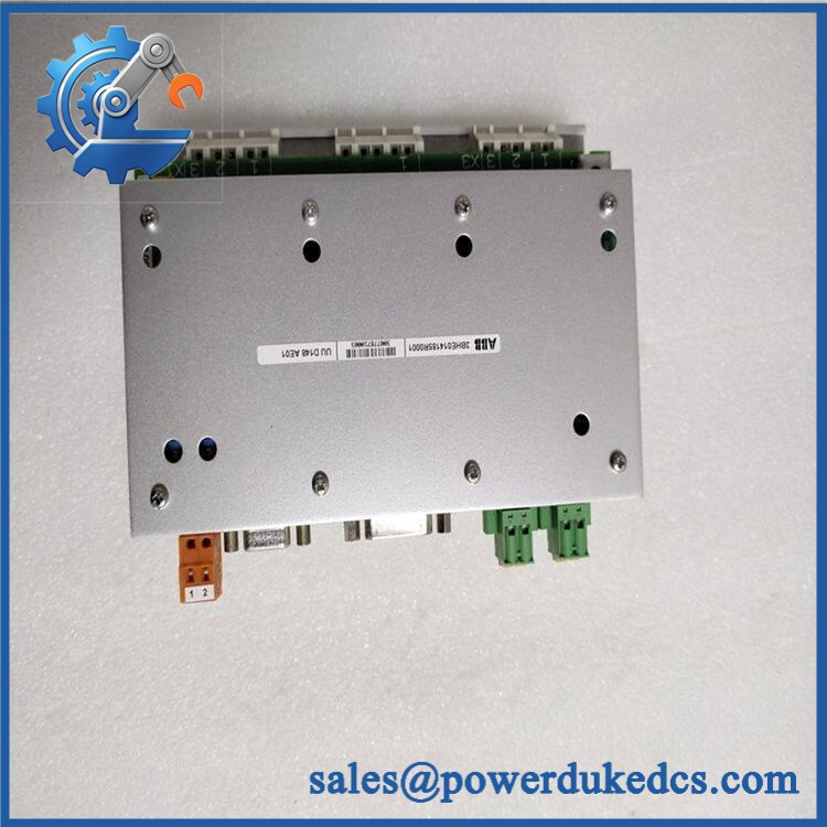
ABB UUD148AE02 3BHE014185R0002
Module 4: Dynamic Emergency Swap & Configuration Guide
1. Pre-Swap Prep — Secure the Current Circuit First
Shut down the using the approved lockout/tagout procedure. ABB’s service procedure then calls for switching off MCB-Q306 to remove the 3-phase 400 V input to the AC/DC converter and waiting approximately 5 minutes for the industrial PC shutdown. The UPS battery supply is then interrupted through the specified battery-service procedure.
Before disconnecting the current-transducer board, identify the applicable current measurement circuit and electrical drawing. ABB specifically warns about an open current loop and requires the terminals on the current-transducer side to be short-circuited before disconnecting the board cables. Use the approved shorting facility, ESD protection, insulated tools, and a calibrated meter.
2. Removal — Disconnect the Board Only After the Current Circuit Is Secured
With the de-energized and the relevant current terminals safely shorted, photograph the board position and all connections. Disconnect the current-transducer board cabling, release the retaining hardware, and remove the UUD148AE02 from its installed control position without stressing the PCB or connector assemblies. Keep the original board beside the replacement for revision, jumper, and connector comparison.
3. Installation & Configuration — Match Every Jumper to the Drawing
Install UUD148AE02 / 3BHE014185R0002 in the identical position and reconnect the cables according to the electrical documentation. This step must not be improvised: ABB’s service table explicitly states “Set jumpers according to electrical drawings” for this component. Verify every jumper against the removed board and the current drawing before restoring power.
Do not assume that a board carrying the same UUD148AE02 identification can be configured identically for every installation. The current-transducer arrangement and jumper settings are application-specific.
4. Power-On Self-Test (POST) — Validate Current Feedback Before Release
Restore the auxiliary power through the normal commissioning sequence. Confirm that the control system starts without current-measurement or control-component diagnostic faults. Then verify the current-feedback values using the approved test procedure and compare the measured values against a calibrated reference.
Do not begin with a full-power converter run. Prove the current-feedback path first, followed by the applicable converter functional test. ABB’s own replacement procedure categorizes this board within the control-component architecture and provides a dedicated service sequence for the AE02 current-transducer board.
Module 5: Quality Assurance & Testing SOP
The ABB / 3BHE014185R0002 requires controlled current-feedback testing before release to critical-spares inventory.
- Identity verification: Record , 3BHE014185R0002, UU D148 AE02: 1A designation, serial number, and hardware markings.
- OEM anti-counterfeit visual inspection: Inspect ABB labels, PCB markings, connector construction, component layout, fasteners, and manufacturing identifiers.
- Mechanical inspection: Check PCB condition, connectors, mounting points, edge contacts, contamination, corrosion, and evidence of overheating.
- Jumper verification: Compare every jumper position against the applicable electrical drawing. ABB expressly lists jumper setup as a required replacement task.
- Power-on self-test (POST): Install the board in an approved test environment and verify normal controller startup and absence of current-transducer-related diagnostic faults.
- Current-loop safety inspection: Confirm the current-measurement circuit is correctly secured before energization. ABB’s replacement procedure specifically requires the current-transducer terminals to be short-circuited before cable disconnection.
- Current-signal simulation: Apply approved calibrated current-feedback signals and verify the corresponding control-system measurements.
- Full-range feedback test: Test representative low, nominal, and high current-feedback conditions within the approved test limits.
- Polarity/phase verification: Confirm that each current feedback channel corresponds to the correct phase and direction before converter operation.
- Protection-path verification: Confirm that current-measurement diagnostics and applicable protection logic respond correctly during controlled simulation.
- Extended runtime test: Monitor feedback stability for intermittent signal loss, drift, abnormal heating, or connector-related faults.
- Final QC record: Retain serial-number photographs, jumper-position photographs, current-injection measurements, diagnostic results, test date, technician sign-off, and final pass/fail status.
ABB’s service manual classifies as a serialized current-transducer control component that can be replaced by the customer under the documented procedure.
Module 6: Maintenance & Reliability FAQ
1. Is ABB a direct replacement, or does it require a firmware flash?
is a current-transducer control board, not the main application processor. A firmware flash should therefore not be assumed as part of a normal board exchange. The critical compatibility checks are the exact 3BHE014185R0002 identification, board revision, connector arrangement, current-transducer circuit, and especially the required jumper positions. ABB explicitly requires jumper settings to be established from the electrical drawings.
2. Is it safe to hot-swap while the is running?
No. ABB’s documented procedure requires the to be shut down, the associated 24 V supply interrupted, and the current-transducer terminals short-circuited before the board cables are disconnected. Never remove this board as though it were a live-swappable PLC I/O card.
3. Will replacing cause my current program to be lost?
The is identified as a current-transducer control component, not the primary application-storage controller. Replacing it should therefore not inherently erase the application. Nevertheless, back up the controller configuration and record the current-measurement setup before maintenance.
4. What should I verify after installing ?
Verify the complete jumper configuration against the electrical drawings, current-loop wiring, connector seating, phase assignment, current-feedback values, and diagnostics. Then perform the prescribed converter functional test. A board that passes a basic power-up check has not yet proven that its current measurement is correctly scaled or assigned.
5. What are the warranty terms if the unit fails post-installation?
Warranty should follow the commercial terms for the exact supplied unit and condition. Retain the serial number, pre-shipment test record, jumper photographs, current-injection results, installation date, and diagnostic records. These records are valuable when separating a board defect from an incorrect jumper setting, open current circuit, wiring fault, or sensor-side problem.











 Start Chat


