

Description
- Brand: ABB
- Full Model Number: XC32L1-A2
- Documented Base Type: XC32L1
- Product Family: ABB Control AC 31
- Product Type: Configurable I/O Extension
- Core Function in System: Expansion of distributed binary I/O for AC31 central or remote units
- Digital Inputs: 32 configurable PNP inputs
- Digital Outputs: 32 transistor outputs
- Nominal I/O Voltage: 24 VDC
- Input Current: 4 mA at 24 VDC
- Input Filtering: Configurable, minimum 8 ms
- Input Isolation: 1500 VAC
- Output Load: 0.5 A per output pair
- Total Output Current: 8 A
- Output Protection: Thermal overload and short-circuit protection
- Output Switching Frequency: Up to 100 Hz for resistive loads
- Bus Compatibility: CS31 or Modbus remote-unit architectures; AC31 central units
- Weight: 220 g
- Condition & Lead Time: Stock condition subject to inspection; emergency dispatch available subject to order confirmation
ABB’s official AC31 documentation identifies XC32L1 as a configurable binary I/O extension with 32 inputs and 32 transistor outputs, operating at 24 VDC. It can be used with AC31 40/50-series central units, CS31 extensible remote units, and Modbus extensible remote units. ABB also specifies 1500 VAC input/output isolation, 4 mA input current at 24 VDC, configurable input filtering with an 8 ms minimum, and 8 A total output current.
Part-number note: ABB’s primary technical document identifies the base product as XC32L1; the supplied XC32L1-A2 suffix appears in secondary inventory records. The electrical specifications below are therefore based on ABB’s documented XC32L1 platform rather than treating the -A2 suffix as a separately verified electrical variant.
Module 3: Technical Intro & Downtime Impact
A failed distributed I/O extension can remove dozens of field signals from the controller at once. One moment, the AC31 system is scanning permissives, limit switches, valve feedback, and actuator commands; after a hardware fault, an entire field section can appear unavailable. , based on the documented hardware, provides 32 configurable 24 VDC inputs and 32 transistor outputs for distributed I/O expansion. ABB states that the extension can be connected to AC31 40/50-series central units or to CS31 and Modbus extensible remote units.
For MTTR, the channel count and electrical behavior matter more than software features. Each input is a 24 VDC PNP input drawing 4 mA, with configurable filtering down to 8 ms minimum. Each output supports up to 0.5 A per output pair, with 8 A total charging current, thermal short-circuit/overload protection, and a 100 Hz switching frequency for resistive loads. ABB also specifies 1500 VAC isolation between the I/O and electronics. The extension itself is only about 220 g, but cabinet accessibility and pre-wiring determine the actual field replacement time. (Do not assume the -A2 suffix changes these figures without checking the physical nameplate and site documentation.)
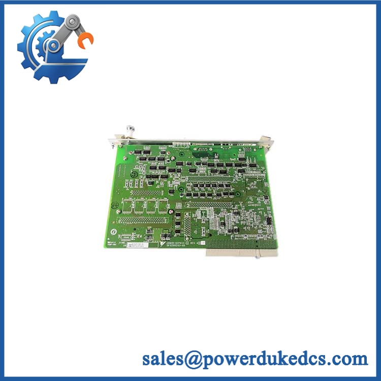
ABB XC32L1-A2.0
Module 4: Dynamic Emergency Swap & Configuration Guide
1. Pre-Swap Prep — Capture the Entire 32-Channel Allocation
Place the affected I/O section into the approved maintenance condition and isolate power before disconnecting the extension. ABB explicitly states that /XC32L2 extensions must be connected or disconnected without power supply. Record the unit’s full marking, bus address, upstream controller or remote-unit identification, channel allocation from 0–31, output assignments, and pre-wiring connector positions. Photograph both HE10 connectors and the local 24 VDC supply connection.
2. Removal — Disconnect the Bus and 24 VDC Supply Before Extraction
is an I/O extension assembly with HE10 interfaces, rather than a standard removable PLC rack card. ABB identifies one connector for connection to the central/remote unit or preceding extension, while separate HE10 connectors carry channels 0–15 and 16–31.
After zero-voltage verification, remove the external 24 VDC connection where fitted, disconnect the field pre-wiring connectors, then release the mounting hardware. Withdraw the extension without twisting the HE10 connectors. Keep the wiring organized by channel group; a swapped upper/lower connector can move an entire 16-channel block.
3. Installation & Configuration — Restore the Bus Position and Channel Mapping
Install the replacement in the original position and reconnect the upstream bus/interface exactly as documented. Restore the 24 VDC external supply where the existing wiring uses it. ABB notes that the local 24 VDC connection is required when 24 VDC is not carried by the pre-wiring cable or when the total input current through the HE10 connector exceeds 1 A.
Then verify the addressing configuration. reserves two address places: one input and one output. ABB documents maximum quantities based on the host architecture: up to 6 extensions on 40/50-series central units, 3 on CS31 remote units, and 5 on Modbus remote units. The controller must therefore recognize the extension at the original bus position before field signals are released.
4. Power-On Self-Test (POST) — Verify All 64 Channels
Restore power and use the built-in channel indicators to confirm the extension initializes correctly. provides a selector allowing the front indication to display either channels 0–15 or 16–31. Check both groups.
Next, force known 24 VDC input states across representative channels and verify the correct input bits at the controller. Exercise representative outputs with controlled loads and confirm switching, load response, and diagnostic behavior. A healthy power indication is insufficient; the final acceptance criterion is correct channel-to-address mapping across the full 0–31 input/output allocation.
Module 5: Quality Assurance & Testing SOP
Each ABB -A2 / should receive mechanical, electrical, and communication-interface testing before shipment.
- OEM anti-counterfeit visual inspection: Verify ABB markings, identification, suffix/revision marking, PCB construction, HE10 connectors, terminal interface, and manufacturing quality.
- Exact identification verification: Record the physical marking as and document that ABB’s primary technical specification covers the base platform.
- Mechanical inspection: Check connector pins, mounting points, housing, indicator LEDs, selector switch, PCB edges, contamination, corrosion, and evidence of repair.
- 24 VDC power test: Apply the specified supply under controlled laboratory conditions and verify normal startup.
- Input-channel test: Exercise all 32 PNP inputs at appropriate 0/1 voltage levels and verify correct channel indication and controller data.
- Input filtering test: Verify configured filtering and confirm a response time no lower than the documented 8 ms minimum filtering time for the selected configuration.
- Output-channel test: Exercise all 32 transistor outputs with approved loads and verify switching behavior.
- Output-load test: Verify applicable output loading up to 0.5 A per output pair, while maintaining the documented total-current limits.
- I/O full-range simulation: Cycle every input and output channel through its intended states and compare actual channel status with the controller image table.
- Short-circuit/overload verification: Where the test fixture supports it, verify the documented thermal protection and diagnostic response without exceeding laboratory safety limits.
- Isolation test: Verify the applicable 1500 VAC isolation requirement using an approved hipot procedure and controlled test limits.
- Bus-interface test: Connect the extension to a compatible /CS31/Modbus test environment and verify correct addressing and data exchange.
- Extension-chain test: Where applicable, test the unit as part of a multi-extension chain and verify that the additional I/O addresses remain correct.
- LED/display test: Verify indication for channels 0–15 and 16–31 using the selector switch.
- Extended stability test: Maintain representative input/output activity and monitor for intermittent channel loss, thermal behavior, unexpected resets, or communication errors.
- Final QC record: Record part marking, host architecture tested, bus position, input/output test results, isolation results, load conditions, test duration, photographs, technician sign-off, and packaging condition.
Module 6: Maintenance & Reliability FAQ
1. Is ABB -A2 a direct drop-in replacement, or does it require a firmware flash?
is an I/O extension, not a CPU. ABB’s documentation describes it as a configurable binary I/O extension for central units and CS31/Modbus remote units. A firmware flash is therefore not normally the defining replacement procedure. The important checks are the exact physical variant, host architecture, bus position, addressing, connector layout, and field I/O mapping.
2. Is it safe to hot-swap -A2 while the system is running?
No. ABB explicitly states that and XC32L2 extensions must be connected or disconnected without power supply. Isolate the 24 VDC supply and the associated controller/remote-unit power as required before removing the extension.
3. Will replacing -A2 cause my current program or configuration to be lost?
The extension itself does not contain the main PLC application. The greater risk is incorrect I/O addressing or channel mapping after replacement. Record the extension’s bus location, input/output address allocation, channel assignments, output logic, and any associated controller configuration before removal. ABB specifies that an consumes one input and one output address place in the host architecture.
4. What should I verify before commissioning the replacement?
Verify the physical marking, 32 configurable inputs, 32 transistor outputs, 24 VDC supply, connector arrangement, host controller type, and bus position. ABB specifies 4 mA input current at 24 VDC, 0–5 V for logic 0, 15–30 V for logic 1, and 1500 VAC I/O isolation. Then test all four 16-channel groups logically: inputs 0–15, inputs 16–31, outputs 0–15, and outputs 16–31.
5. What are the warranty terms if the unit fails after installation?
Warranty coverage should be stated on the quotation or sales order for the specific serialized unit. Retain the incoming inspection report, exact part marking, bus-address record, channel map, 24 VDC measurements, I/O test results, and commissioning report. For an distributed-I/O extension, those records help distinguish a failed extension from a pre-wiring, bus-address, power-supply, or field-device problem.











 Start Chat


