

Description
- Brand: ABB
- Full Model Number: XVC767AE102
- ABB Part Number: 3BHB007209R0101
- Product Type: Current Measurement Scale Board
- Lifecycle Status: Legacy industrial spare; exact application and availability require verification
- Core Function in System: Current-measurement signal scaling and conditioning in ABB high-power drive systems
- Top 3 Hardcore Specs: Current measurement scaling; analog signal conditioning; plug-in PCB construction
- Typical Application: ABB medium-voltage and high-power drive control systems
- Form Factor: Plug-in electronic circuit board
- Reported Net Weight: Approximately 0.65 kg
- Cooling: Passive
- Condition & Lead Time: New replacement stock subject to physical and revision verification; emergency dispatch based on confirmed inventory
Available product records identify XVC767AE102 / 3BHB007209R0101 as a CURRENT MEAS. SCALE BOARD, intended to condition and scale current-measurement signals in ABB high-power drive equipment. Secondary records conflict with some descriptions of this exact part, so the complete part-number and PCB-marking match should control procurement.
Module 3: Technical Intro & Downtime Impact
A current-measurement scaling board can become a single point of failure for converter control when the drive controller no longer receives a valid current feedback signal. ABB XVC767AE102, 3BHB007209R0101 is identified in available technical records as a current measurement scale board, where its role is to condition measurement signals before they are used by the associated drive-control system. A failure can therefore appear as incorrect current feedback, protection trips, converter inhibit, or loss of normal regulation.
For MTTR reduction, the most reliable identifiers are the complete XVC767AE102 / 3BHB007209R0101 combination, the current-measurement function, and the plug-in PCB format. A secondary technical listing reports approximately 0.65 kg net weight and passive cooling. Public records do not provide a sufficiently authoritative common set of input current range, output scaling ratio, supply voltage, accuracy, or bandwidth for this exact board. —Those parameters should be taken from the drive schematic and the failed board’s engineering documentation rather than copied from unrelated I/O or semiconductor listings.
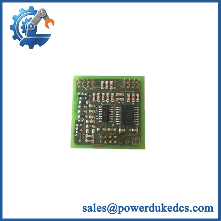
ABB XVC767AE102 3BHB007209R0101
Module 4: Dynamic Emergency Swap & Configuration Guide
1. Pre-Swap Prep — Freeze the current-feedback configuration
- Place the ABB drive in the approved maintenance state.
- Isolate the drive and follow the site’s lockout/tagout procedure.
- Verify absence of hazardous voltage before accessing the control cabinet.
- Record XVC767AE102 / 3BHB007209R0101 and the PCB revision.
- Photograph the board orientation, connector positions, and adjacent cards.
- Record current-sensor inputs, scaling connections, jumpers, and terminal assignments.
- Save the existing drive parameters and current-feedback configuration.
- Use ESD protection and an antistatic work surface.
2. Removal — Handle the plug-in PCB correctly
- Confirm the cabinet is electrically safe.
- Identify and label each board connection before disconnection.
- Release the board’s retaining hardware or extraction mechanism.
- Withdraw the PCB evenly from its card guide or mating connector.
- Do not pull on measurement wiring or individual connector conductors.
- Place the removed board immediately into ESD-safe packaging.
- Inspect the backplane and mating connector for bent contacts, oxidation, contamination, or thermal damage.
The available technical listing describes the XVC767AE102 as a plug-in PCB used in control cabinets or enclosures, supporting a card-level replacement procedure rather than a DIN-rail power-supply replacement.
3. Installation & Configuration — Preserve current-signal scaling
- Verify ABB / 3BHB007209R0101 before insertion.
- Confirm PCB revision against the failed board.
- Verify the current-sensor input arrangement and connector pinout.
- Install the board in the identical rack/card position.
- Seat the connector completely without forcing the PCB.
- Restore all documented jumpers, switches, or hardware configuration settings.
- Reconnect current-measurement signals exactly according to the approved drive schematic.
- Restore the original drive current-scaling parameters.
- Verify phase/channel assignment before energization.
- Do not substitute specifications from a different XVC767 variant.
4. Power-On Self-Test (POST) — Validate current feedback
- Restore auxiliary power according to the drive commissioning procedure.
- Check the controller for board-recognition or hardware diagnostics.
- Verify that no persistent measurement or scaling fault remains.
- Confirm current-feedback channels report plausible zero-current values before load is applied.
- Apply a controlled test signal where the commissioning procedure permits secondary simulation.
- Compare displayed current against the calibrated reference.
- Verify all applicable protection thresholds and current-feedback alarms.
- Perform a controlled no-load or minimum-load drive test.
- Compare phase-current readings before returning the drive to normal operation.
There is no reliable public evidence for a universal standalone LED sequence for this exact board. POST should therefore be based on the host drive’s diagnostics, measured current-feedback values, and the approved commissioning procedure.
Module 5: Quality Assurance & Testing SOP
This board should be tested as a precision signal-conditioning component. Physical appearance alone cannot establish that the current-scaling circuit is functioning correctly.
1. OEM identity verification
- Verify ABB
- Verify
- Verify 3BHB007209R0101
- Compare PCB markings and revision codes
- Compare connector arrangement and board layout
- Perform OEM anti-counterfeit visual inspection
- Photograph all identification markings
2. Physical inspection
- Inspect PCB surfaces for corrosion, contamination, and cracked components
- Check connector housings and contacts
- Inspect card-edge contacts for oxidation or mechanical damage
- Check mounting points and extraction hardware
- Inspect for thermal discoloration
- Look for evidence of unauthorized component replacement or PCB rework
- Verify passive-cooling paths are unobstructed
3. Electrical screening
- Perform board continuity checks using an approved test procedure
- Inspect power and reference paths
- Check connector pin integrity
- Verify ground/reference continuity where applicable
- Check for abnormal resistance or short-circuit conditions on accessible circuits
- Do not apply arbitrary hipot voltages to populated signal-conditioning electronics
4. Functional testing
- Install the board in a compatible ABB drive test environment where available
- Perform power-on self-test
- Confirm board recognition by the host system
- Apply calibrated current-simulation signals
- Verify current-measurement scaling
- Check signal linearity across the approved measurement range
- Verify zero-current offset
- Check phase/channel correspondence
- Verify alarm and protection thresholds
- Perform I/O full-range simulation on all applicable measurement channels
- Compare measured values with calibrated test-equipment references
- Record input signal, scaled output, deviation, hardware revision, and final result
5. Final QC release
- Independent QC sign-off
- ESD-safe packaging
- Connector protection
- Final cross-check of
- Retain calibration and functional-test records
- Retain inspection photographs
- Release only after current-feedback verification passes
The available technical record describes the part as a current measurement scaling board and reports passive cooling with an approximate 0.65 kg net weight. Those characteristics should be treated as identification aids; exact electrical scaling values must be verified against the installed drive documentation.
Module 6: Maintenance & Reliability FAQ
Q1. Is ABB 3BHB007209R0101 a direct drop-in replacement, or does it require a firmware flash?
No firmware flash should be assumed. This is identified as a current-measurement scale board rather than a standalone PLC processor. The critical checks are board revision, connector arrangement, current-sensor interface, rack position, and drive-specific scaling parameters.
Q2. Is it safe to hot-swap the while the system is running?
Do not assume hot-swap capability. The board interfaces with current-measurement circuitry associated with a high-power drive. Unless the exact ABB drive documentation provides an approved energized replacement procedure, isolate the drive and verify absence of hazardous voltage before removing the board.
Q3. Will replacing the cause my current program or configuration to be lost?
The board itself is not the primary application-program storage device. The main risk is incorrect current-feedback scaling after replacement. Back up the drive configuration and record sensor type, channel assignment, scaling coefficients, offsets, jumpers, and related protection thresholds before removal.
Q4. What should I verify before ordering this ABB board?
Verify all three identifiers: , 3BHB007209R0101, and the PCB revision. Then compare connector layout, rack position, current-sensor interface, and the drive schematic. This is especially important because some secondary sources incorrectly describe the same part number as a general I/O or semiconductor product.
Q5. How should the replacement board be tested before the drive returns to production?
Use a controlled test rack or compatible ABB drive environment. Verify board recognition first, then apply calibrated current-simulation signals and check zero offset, scaling, phase assignment, linearity, alarms, and protection thresholds. Do not rely solely on a successful power-up; the purpose of the board is accurate current measurement, so the measurement chain itself must be proven.











 Start Chat


