

Description
- Brand: ABB
- Full Model Number: XVC767AE105 / 3BHB007209R0105
- Lifecycle Status: Legacy power-electronics hardware
- Core Function in System: IGCT gate-drive interface and switching-control circuitry
- Top 3 Hardcore Specs: XVC767AE105 board designation; 3BHB007209R0105 ABB article number; fiber-isolated gate-control interface
- System Association: ABB high-power converter and drive power stages
- Form Factor: Power-electronics control/gate-drive PCB
- Signal Interface: Isolated control interface, typically fiber-optic in the associated converter architecture
- Associated Semiconductor Family: ABB IGCT power devices
- Condition & Lead Time: New OEM, new old stock, or tested replacement; emergency availability subject to confirmed physical inventory
Available part-specific references identify XVC767AE105 / 3BHB007209R0105 as an ABB IGCT gate-drive unit board. The evidence is primarily from specialist inventory records rather than a currently indexed ABB product page, so exact application matching should be confirmed against the installed drive documentation before ordering.
Module 3: Technical Intro & Downtime Impact
At 3 AM, a failed gate-drive board can look like a much larger converter failure. The controller may remain alive while one power-switching channel no longer receives valid gate commands, producing converter trips, missing switching pulses, or phase-specific faults. ABB XVC767AE105, article 3BHB007209R0105, is identified in available part references as an IGCT gate-drive board used with ABB high-power power-electronics equipment.
The important MTTR issue is not simply getting another PCB into the cabinet. Gate-drive hardware is tied to a specific semiconductor and control architecture, and the available technical listing describes fiber-optic control signaling, dedicated DC power requirements, and status/protection feedback. The replacement therefore should be matched by exact article number, hardware revision, connector arrangement, optical interface, and associated IGCT type. (For older converter cabinets, inspect optical connectors and the gate-drive power supply before declaring the board itself defective.)
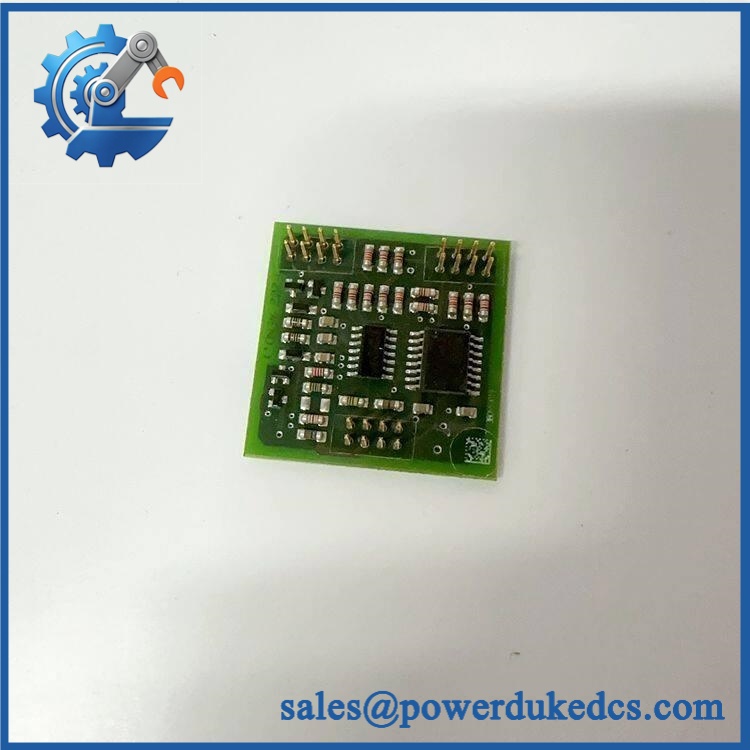
ABB XVC767AE105 3BHB007209R0105
Module 4: Dynamic Emergency Swap & Configuration Guide
1. Pre-Swap Prep — Identify the Power-Semiconductor Pair
Place the converter in its approved maintenance state and complete the manufacturer’s isolation procedure. Verify that the DC link and associated energy-storage circuits are fully discharged before accessing the power section. Record XVC767AE105 / 3BHB007209R0105, PCB revision, slot or phase position, fiber connections, gate connections, and the identification of the associated IGCT.
Available part references describe this assembly as a dedicated IGCT gate-drive board, so the semiconductor pairing should be established from the converter drawing rather than from appearance alone.
2. Removal — Protect the Optical and Gate Interfaces
After electrical isolation has been verified, photograph the complete board before disconnecting anything. Disconnect the fiber-optic interfaces using the approved handling method; never bend, sharply coil, or pull on the fiber cable. Remove the gate and auxiliary connections, release the board retainers, and withdraw the XVC767AE105 squarely from its mounting position.
Inspect the optical connectors, gate interface, auxiliary supply contacts, and adjacent power-stage components for contamination, carbon tracking, heat discoloration, or physical damage.
3. Installation & Configuration — Match Fiber Channel and Gate Assignment
Install in the same physical position. Reconnect every fiber, auxiliary-power, and gate interface according to the original electrical and fiber-routing documentation. Verify the board revision and any hardware configuration links before energization.
Do not invent jumper, DIP-switch, or address values from generic listings. Gate-drive configuration must follow the exact converter drawing and the connected IGCT type. Specialist documentation describes this part as an isolated gate-drive interface for high-power IGCT switching devices.
4. Power-On Self-Test (POST) — Prove Gate Command and Fault Feedback
Restore auxiliary power first and inspect the drive diagnostics. Confirm that the board initializes without gate-drive, optical-link, auxiliary-power, or protection alarms. Verify communication between the controller and gate-drive unit.
Before enabling the full power stage, perform the approved low-energy gate-pulse test. Check the gate waveform with appropriately rated isolated instrumentation and verify the expected feedback and protection response. Do not proceed to full converter voltage until the command path has passed the commissioning test.
Module 5: Quality Assurance & Testing SOP
The ABB / 3BHB007209R0105 should receive a controlled gate-drive acceptance test rather than a basic power-up.
- Identity verification: Record , 3BHB007209R0105, PCB revision, serial number, and associated IGCT identification.
- OEM anti-counterfeit visual inspection: Inspect ABB labels, PCB markings, component placement, optical connectors, gate terminals, and manufacturing identifiers.
- Mechanical inspection: Check PCB condition, edge contacts, mounting points, optical connectors, gate interface, and retaining hardware.
- Power-on self-test (POST): Energize the board within an approved low-energy test setup and verify startup diagnostics and normal status behavior.
- Auxiliary-supply verification: Confirm the board receives the correct control power specified by the applicable converter documentation. The available technical listing identifies dedicated DC power requirements rather than a universal supply value.
- Fiber-optic interface test: Verify optical transmit/receive paths, connector condition, and stable communication with the parent control system.
- Gate-command simulation: Apply controlled gate commands through the approved test fixture and verify the corresponding output behavior.
- Gate-waveform verification: Measure gate pulses using isolated instrumentation and compare timing, amplitude, polarity, and waveform characteristics with the applicable equipment specification.
- Protection-feedback test: Simulate approved fault conditions and confirm that gate-drive status and fault feedback reach the control system correctly.
- Phase/channel verification: Confirm that the board’s gate output corresponds to the correct phase or power-device position.
- Thermal observation: Monitor the board during representative operation for abnormal temperature rise or unstable behavior.
- Extended runtime test: Run repeated switching-control cycles to expose intermittent optical links, unstable gate drive, or thermal faults.
- Final QC record: Retain identification photographs, revision data, fiber test results, waveform captures, protection-test results, test date, technician sign-off, and final pass/fail disposition.
The strongest available part-specific evidence describes as an IGCT gate-drive unit board with an isolated control interface.
Module 6: Maintenance & Reliability FAQ
1. Is ABB a direct replacement, or does it require a firmware flash?
Do not assume a blind replacement. This is gate-drive hardware, not the main application CPU, so a routine firmware transfer should not normally be the first issue. The critical checks are 3BHB007209R0105, hardware revision, optical interface, gate connection, auxiliary supply, and compatibility with the installed IGCT and converter architecture.
2. Is it safe to hot-swap while the converter is running?
No. Treat the board as non-hot-swappable. It participates directly in high-power semiconductor switching, and live removal can interrupt gate control or protection functions. Complete the converter shutdown, isolation, and stored-energy discharge procedure before access.
3. Will replacing cause my current drive program to be lost?
The is identified as a gate-drive board rather than the primary application controller. Replacing the board should not itself erase the main drive application. Even so, back up the converter parameters, control configuration, firmware records, and fault history before replacement.
4. What should I verify after installing ?
Verify the exact board identification, revision, auxiliary supply, fiber-optic communication, gate connection, phase assignment, protection feedback, and gate waveform. Then complete the approved low-energy converter test before energizing the power stage. A board that powers up correctly has not necessarily passed the gate-drive acceptance test.
5. What are the warranty terms if the unit fails post-installation?
Warranty should follow the commercial terms for the exact supplied unit and condition. Retain the serial number, pre-shipment test report, board photographs, fiber-interface test results, gate-waveform captures, installation date, and commissioning record. Those records help distinguish a board failure from an optical-link problem, incorrect gate assignment, auxiliary-power fault, or an underlying IGCT failure.











 Start Chat


