

Description
- Brand: ABB
- Full Model Number: XVC768AE117
- ABB Part Number: 3BHB007211R0117
- Product Type: Current Measurement Scaling Subprint (SCA)
- Product Family: ACS6000 Medium-Voltage Drive
- Lifecycle Status: Legacy ACS6000 installed-base spare
- Core Function in System: Scales and conditions inverter current feedback for the ACS6000 control system
- Top 3 Hardcore Specs: ±4,500 A measurement range; 1,648 A rated RMS current; 11 MVA peak ACS6000 application
- Measurement Range: -4,500 to +4,500 A
- Rated Current: 1,648 A RMS
- Matching Inverter: ACS6000 11 MVA peak
- Board Designation: XV C768 AE117 SCA
- Interface Role: Current measurement feedback / scaling
- Condition & Lead Time: Tested inventory or factory-sealed stock; emergency dispatch subject to confirmed availability
ABB commissioning documentation identifies XV C768 AE117 / 3BHB007211R0117 as an SCA current-measurement subprint for the ACS6000 11 MVA peak configuration, with a -4,500 to +4,500 A measurement range and 1,648 A RMS rated current.
Module 3: Technical Intro & Downtime Impact
A current-feedback board failure on a high-power drive can stop an otherwise healthy converter from operating normally. The control system depends on accurately scaled current feedback for regulation, protection, diagnostics, and inverter control. When the measurement path becomes unreliable, symptoms may include current-feedback faults, incorrect displayed current, converter trips, or an inhibited startup. ABB XVC768AE117 3BHB007211R0117 is the SCA subprint assigned to a specific high-power configuration.
The numbers are important here. ABB identifies this SCA with a ±4,500 A measurement range, 1,648 A RMS rated current, and an application. The same commissioning documentation lists different XVC768 SCA part numbers for 9, 7, 5, and 3 MVA configurations, so substituting an apparently similar current-scaling board without checking the drive rating can create a serious scaling mismatch. During an outage, exact SCA identification is therefore a direct MTTR control measure.
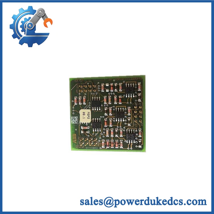
ABB XVC768AE117 3BHB007211R0117
Module 4: Dynamic Emergency Swap & Configuration Guide
1. Pre-Swap Prep — identify the exact current-scaling version
Place the drive in the plant-approved maintenance state and complete the required LOTO procedure. Verify the DC link and other hazardous circuits are at the approved safe level before accessing the electronics. Photograph the XVC768AE117 marking, 3BHB007211R0117 part number, mounting position, connectors, and current-feedback wiring. Record the inverter rating and existing SCA designation. This step is critical because ABB assigns different XVC768 SCA boards to different current ratings.
2. Removal — preserve the measurement path
After electrical isolation, label the current-feedback connections and connector locations before disconnecting them. Release the subprint from its carrier or mating interface using the installed mechanical arrangement and withdraw it without forcing the PCB. Inspect connector contacts, card guides, and adjacent current-measurement circuitry for contamination, overheating, or mechanical damage. Check the existing wiring against the commissioning documentation before transferring it to the spare.
3. Installation & Configuration — match the SCA to the inverter rating
Install XVC768AE117 in the same position and reconnect the current-measurement interfaces exactly as documented. Confirm that the drive is the corresponding 11 MVA peak configuration before energization. The ABB commissioning table assigns XVC768 AE117 / 3BHB007211R0117 to -4,500…+4,500 A measurement and 1,648 A RMS rated current. Do not substitute AE101, AE102, AE105, AE106, or other SCA variants merely because they share the XVC768 family.
4. Power-On Self-Test (POST) — validate current scaling before enabling the inverter
Restore control power and check the diagnostic system for current-measurement or SCA-related faults. Confirm that measured current is sensible at zero-current conditions and during a controlled commissioning test. Compare the displayed feedback against calibrated test equipment or the approved measurement reference. Check all three current channels as applicable and verify there is no phase-to-phase mismatch. Only after the current-feedback path is stable should normal inverter operation be permitted.
Module 5: Quality Assurance & Testing SOP
The XVC768AE117 should be tested as a precision current-measurement scaling board.
- OEM Anti-Counterfeit Visual Inspection: Verify ABB markings, XVC768AE117, 3BHB007211R0117, PCB layout, connectors, component placement, labels, and revision markings.
- Serial and Identity Traceability: Record the complete board identification and photograph the nameplate or printed board markings.
- Mechanical Inspection: Check PCB edges, mounting points, connector contacts, card guides, and retaining hardware.
- Power Verification: Apply the specified control supply through a controlled test fixture and verify normal initialization.
- Power-On Self-Test (POST): Check all available status and diagnostic indications during startup.
- Current-Signal Simulation: Apply controlled representative current-feedback signals through the appropriate test interface and verify measurement response.
- Full-Range Scaling Test: Verify the documented -4,500 to +4,500 A measurement range through the approved scaled test method.
- Rated-Current Verification: Confirm correct scaling around the 1,648 A RMS rated-current reference for the 11 MVA peak configuration.
- Phase-Balance Check: Verify equivalent feedback paths respond consistently under matched simulated inputs.
- Polarity Verification: Confirm positive and negative current direction are represented correctly by the measurement system.
- Zero-Offset Check: Verify the current-feedback value returns to the expected zero point with no applied current.
- Control-System Recognition Test: Confirm the control system accepts the current measurement without persistent hardware diagnostics.
- Fault-Diagnostic Test: Where the test fixture permits, simulate a measurement-path fault and verify expected diagnostic behavior.
- Extended Powered Test: Monitor for measurement drift, intermittent communication, unstable values, or abnormal temperature during extended operation.
- Final QC Record: Document the SCA designation, part number, test range, reference equipment, measured results, photographs, and QC approval.
ABB’s commissioning documentation explicitly warns that the SCA marking should be used to determine the correct current rating and corresponding inverter type. This is particularly important for the , where XVC768 variants cover multiple MVA ratings.
Module 6: Maintenance & Reliability FAQ
1. Is the 3BHB007211R0117 a direct drop-in replacement, or does it require a firmware flash?
This is a current-measurement scaling subprint, not the primary application controller. A conventional firmware flash is therefore not normally the main replacement issue. The critical check is whether the SCA matches the installed drive rating. ABB assigns XVC768 AE117 / 3BHB007211R0117 to the 11 MVA peak configuration with a ±4,500 A measurement range and 1,648 A RMS rated current.
2. Is it safe to hot-swap the while the system is running?
Do not assume live removal is permitted. The SCA is part of the current-measurement path of a high-power medium-voltage converter. Follow the specific maintenance procedure and isolate hazardous power circuits before removing the board unless the documented procedure explicitly authorizes otherwise.
3. Will replacing this current-scaling board cause my current drive program to be lost?
Replacing the SCA does not normally replace the main control application. The important issue is maintaining the correct hardware-specific current scaling and drive configuration. Back up the drive parameters, commissioning data, inverter type, and current-feedback configuration before replacement.
4. What should I verify after installing the replacement?
First verify that the installed is the correct 11 MVA peak configuration for AE117. Then check current feedback at zero, low, medium, and controlled high test levels. Confirm phase consistency, polarity, scaling, diagnostics, and displayed current against the approved reference. ABB’s commissioning documentation specifically uses the SCA type to determine the appropriate inverter configuration.
5. What are the warranty terms if the unit fails post-installation?
Warranty coverage should be tied to the supplied serial number and documented condition. Coverage should distinguish board-level hardware defects from failures caused by incorrect installation, incompatible configuration, wiring errors, downstream current-sensing faults, overvoltage, ESD, or unauthorized modification. The exact warranty period and return procedure should be stated on the quotation before purchase.











 Start Chat


