

Description
- Brand: ABB
- Full Model Number: XVC768AE117
- ABB Material Reference: 3BHB007211R117
- Lifecycle Status: Legacy / spare-parts support candidate; verify system-specific availability before shutdown planning
- Core Function in System: Current detection and sensing within an ABB industrial drive/control assembly
- Top 3 Hardcore Specs: Current-detection circuitry | Board-level construction | 3BHB007211R117 identification
- Condition & Lead Time: Inventory dependent; emergency shipment available subject to final inspection and order release
- Reported Physical Data: Approx. 1.08 kg; one field listing reports 23 × 25 × 28 cm ABB UFC789AE101 FSCD Board for Frequency Converter Systems
ABB UFC789AE101 Fast Replacement FSCD Board Ready for Dispatch
ABB UFC789AE101 3BHE014023R0101 Coated FSCD Control Board
ABB UFC789AE101 Direct Replacement for 3BHE014023R0101 Systems
ABB UFC789AE101 OEM FSCD Board 3BHE014023R0101 Fast Shipping
Module 2: The 10-Second Maintenance Snapshot (Buyer’s Brief)
Brand: ABB
Full Model Number: UFC789AE101
ABB Product ID: 3BHE014023R0101
Lifecycle Status: OEM catalog item; ABB listing indicates Made To Order
Core Function in System: Coated FSCD board used as a frequency-converter spare part
Top 3 Hardcore Specs: FSCD-BOARD, COATED; Product ID 3BHE014023R0101; Net weight 0.25 kg
Physical Form: Open printed circuit board with mounted electrical connectors
OEM Ordering Detail: Minimum order quantity 1 piece
Condition & Lead Time: Stock condition subject to physical verification; emergency dispatch available for verified inventory
Compatibility Control: Exact ABB type designation and full product ID match required before replacementABB’s published product record identifies as “FSCD-BOARD, COATED”, with Product ID 3BHE014023R0101, a net weight of 0.25 kg, and a minimum order quantity of one piece. The same record marks the item as made to order.Module 3: Technical Intro & Downtime Impact
A failed control board inside a frequency-converter installation can stop a drive train even when the surrounding cabinet hardware remains serviceable. The ABB , identified by ABB Product ID 3BHE014023R0101, is specified as a coated FSCD board and is intended as a replacement-level spare rather than a generic control board. Historical shipping records also identify this exact part number as an FSCD board used for frequency converters, making exact part-number verification important before an emergency swap.
For MTTR control, the main advantage is identification accuracy: the technician can verify the ABB type designation against 3BHE014023R0101 before touching the cabinet. ABB’s published specification gives a net weight of 0.25 kg, but does not publish memory capacity, nominal supply voltage, or operating-temperature limits in the cited product record; those values should therefore be taken from the applicable converter documentation rather than guessed. —That distinction matters during a breakdown, because an apparently similar board can carry different firmware, connector assignments, or system configuration.
Module 4: Dynamic Emergency Swap & Configuration Guide
1. Pre-Swap Prep — Isolate and document
Apply the converter manufacturer’s shutdown and electrical isolation procedure.
Verify DC-link discharge and absence of hazardous voltage with a properly rated meter.
Photograph the installed board from multiple angles before removal.
Record the exact / 3BHE014023R0101 identification and every connected cable or plug.
Use an ESD wrist strap and antistatic handling materials.
Have the approved converter wiring diagram and board-layout documentation at the cabinet.2. Removal — Treat it as a board-level replacement
Confirm all external power sources are isolated.
Mark connector positions before disconnecting them.
Release the board’s retaining hardware or mounting points without flexing the PCB.
Withdraw the board evenly from its mating connector or backplane interface.
Inspect the connector contacts for oxidation, contamination, bent pins, or heat damage before installing the replacement.3. Installation & Configuration — Preserve the original hardware state
Compare the replacement’s and 3BHE014023R0101 markings with the removed board.
Install the board in the identical physical orientation.
Reconnect every plug according to the recorded reference photographs and approved wiring documentation.
Preserve any documented jumper, switch, address, or configuration settings exactly as found; do not assume factory defaults are correct.
Do not perform a firmware flash simply because a replacement board is being installed. Firmware compatibility must be established from the system documentation and the installed board revision.4. Power-On Self-Test — Check before returning to process
Re-energize only after the enclosure, grounding, connectors, and protective covers are verified.
Observe the board and converter diagnostic indications during startup.
Look for the expected startup sequence and the absence of persistent fault or error indications.
Confirm converter communication and control status before releasing the drive to the process.
Perform a controlled functional test at no-load or minimum permissible load before returning to normal operation.The available ABB product record describes the item as a coated FSCD board but does not provide a universal LED POST sequence. Use the LED behavior specified for the host converter rather than applying a generic PLC LED interpretation.
Module 5: Quality Assurance & Testing SOP
Our pre-shipment inspection for ABB / 3BHE014023R0101 should treat board identity, physical condition, and electrical integrity as separate acceptance gates.
1. Identity and authenticity inspection
Verify ABB type designation:
Verify Product ID: 3BHE014023R0101
Compare board markings, labels, revision information, and connector arrangement against the documented reference
Conduct OEM anti-counterfeit visual inspection
Photograph serial/identification markings for shipment records
Confirm the board is the FSCD-BOARD, COATED configuration rather than a visually similar board2. Physical inspection
Inspect PCB surface for corrosion, contamination, solder damage, lifted components, and cracked connectors
Check mounting points and connector housings
Inspect conformal/coating coverage for obvious mechanical damage
Verify protective packaging and ESD-safe handling3. Electrical screening
Perform continuity checks where appropriate to the board design
Inspect for visible shorting risks or damaged components
Apply only the test voltage and energized test procedure permitted by the applicable ABB/system documentation
Record measured values rather than relying on a simple pass/fail label4. Functional verification
Perform power-on self-test where a compatible test fixture or host system is available
Check applicable ERR/RUN or equivalent diagnostic indicators
Verify communication or control-path behavior when the board is installed in a valid test environment
Perform I/O full-range simulation only for interfaces actually exposed by the specific system configuration
Record test date, technician, board identification, test conditions, and results5. Final release
QC sign-off after inspection and functional screening
Antistatic bag or equivalent ESD protection
Mechanical cushioning around connectors and exposed PCB edges
Final identification label tied to the inspected part number
Shipment released only after the inspected unit matches / 3BHE014023R0101ABB’s published catalog record confirms the exact designation and identifies the product as a coated FSCD board; it does not define a universal standalone functional-test procedure, so any energized testing should follow the host-system documentation.
Module 6: Maintenance & Reliability FAQ
Q1. Is the ABB a direct drop-in replacement, or does it require a firmware flash?
Do not assume either condition. The replacement must match / 3BHE014023R0101 and the installed system’s applicable board revision and software requirements. A firmware flash should be performed only when the ABB system documentation explicitly requires it. The published ABB record identifies the hardware designation but does not specify a universal firmware version.Q2. Is it safe to hot-swap the while the system is running?
Do not treat this board as hot-swappable by default. The published product information does not establish a universal hot-swap procedure for . Follow the shutdown, isolation, discharge, and ESD requirements for the host frequency-converter system before removing the board. A running converter can retain hazardous stored energy even after incoming power has been removed.Q3. Will replacing this board cause my current program or configuration to be lost?
The safest approach is to assume that board replacement can affect hardware-specific configuration even when the application program is stored elsewhere. Before removal, capture all documented parameter settings, jumper or switch positions, board revisions, and system backups that apply to the converter. After replacement, compare the restored configuration against the pre-failure record before returning the equipment to production.Q4. What should I verify before ordering a replacement?
Check all three identifiers: ABB, , and 3BHE014023R0101. Also compare the board revision, connector arrangement, coating condition, and host-system application. ABB’s catalog specifically identifies 3BHE014023R0101 as the product ID for .Q5. What are the warranty terms if the replacement fails after installation?
Warranty coverage should be confirmed against the supplier’s written sales terms before purchase. For a critical converter spare, retain the original packaging, identification photographs, installation records, test results, and failure diagnostics. Those records make post-installation failure analysis substantially easier and help distinguish a defective board from a cabinet wiring, power, configuration, or host-system fault.packaging/product dimensions; confirm against the actual unit before logistics booking
Module 3: Technical Intro & Downtime Impact
A failed current-detection board can stop a drive from producing trustworthy feedback, trigger protective faults, or prevent restart after a maintenance event. ABB XVC768AE117, also identified by material reference 3BHB007211R117, is listed as a current-detection board associated with ABB drive hardware. When the original board is unavailable, extended troubleshooting can turn a component fault into a much longer production outage.
For MTTR reduction, the key advantage is exact part-number matching rather than changing the control architecture during an emergency repair. The available technical records identify XVC768AE117 / 3BHB007211R117 as the same board reference; however, I did not find a reliable ABB primary source confirming memory capacity, operating-temperature limits, or a universal supply-voltage specification for this exact board. Those values should therefore be checked against the drive schematic and the installed revision before energization. (This matters because similar ABB board references can have materially different electrical roles.)
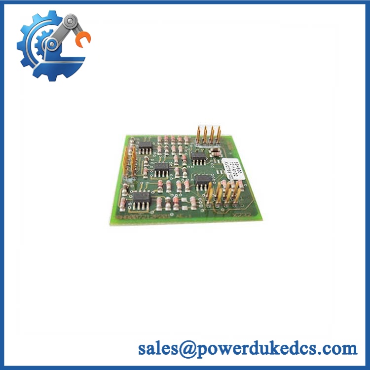
- ABB XVC768AE117
Module 4: Dynamic Emergency Swap & Configuration Guide
1. Pre-Swap Prep — Isolate the Drive Completely
Lock out the incoming power and verify the DC bus has discharged with an approved meter. Use an ESD wrist strap, insulated tools, camera, and the drive electrical drawing. Photograph the existing XVC768AE117 board, connector positions, cable routing, board revision, and all identification labels before touching the assembly.
2. Removal — Disconnect Before Mechanical Release
Because this is identified as a current-detection board, treat it as an internal drive/control-board assembly rather than a generic DIN-rail plug-in. Mark each connector, release the retaining hardware in the sequence specified by the drive assembly, and withdraw the board without flexing attached conductors or stressing current-sensing connections.
3. Installation & Configuration — Match Hardware Exactly
Install the replacement using the same mounting orientation and connector positions. Verify XVC768AE117 and 3BHB007211R117 against the removed board before connection. Do not copy a jumper, resistor setting, calibration adjustment, or parameter value from another ABB board family unless the applicable drive manual explicitly calls for it. Current-sensing circuits are configuration-sensitive; an incorrect connection can produce false feedback or protection trips.
4. Power-On Self-Test — Confirm Feedback Before Release
Re-energize only after the cabinet inspection is complete. Check the drive’s diagnostic display and fault history first, then confirm that current-feedback values appear plausible and stable at zero load. Run the OEM-recommended low-risk test sequence before returning the equipment to process service. Do not rely on a green status indication alone; a current-sensing fault may require verification through measured feedback and drive diagnostics.
Module 5: Quality Assurance & Testing SOP
Our pre-shipment inspection should treat / 3BHB007211R117 as a safety-critical board-level spare, not as a cosmetic inventory item.
- Part-number verification: Confirm ABB identification, marking, 3BHB007211R117 reference, revision labels, connectors, and board condition.
- OEM anti-counterfeit visual inspection: Compare PCB markings, silkscreen quality, component placement, connector construction, label format, and revision information against known ABB hardware.
- Physical inspection: Check for corrosion, cracked solder joints, lifted components, bent connector pins, contamination, repair traces, and mechanical damage.
- Electrical continuity screening: Verify accessible supply, ground, connector, and sensing paths against the approved test documentation.
- Power-on self-test (POST): Where the board is tested within a compatible drive test assembly, check the drive diagnostic state and RUN/ERR or equivalent diagnostic indications after controlled energization.
- Signal simulation: Apply controlled current-feedback simulation or an OEM-approved test-rig stimulus across the applicable sensing path. Record the resulting feedback values rather than accepting a simple power-on pass.
- Functional verification: Confirm that detected current tracks the test stimulus throughout the approved operating range and that abnormal-input protection behaves as expected.
- Final QC record: Record serial/identification data, inspection findings, measured values, test date, technician sign-off, and packaging status before release.
Module 6: Maintenance & Reliability FAQ
1. Is ABB a direct drop-in replacement, or does it require a firmware flash?
The identification should match the board being replaced exactly. Available references associate it with ABB current-detection hardware. A firmware flash should not be assumed necessary for a board-level replacement. However, verify the installed drive type, board revision, and OEM documentation before commissioning because firmware and hardware compatibility can be revision-specific.
2. Is it safe to hot-swap while the system is running?
Do not treat it as a hot-swappable board. The available references describe as a current-detection/control board rather than a standard plug-in I/O device. Isolate power, verify DC-bus discharge, and follow the specific ABB drive service procedure before removal.
3. Will replacing this board cause my current program to be lost?
A board-level replacement does not automatically mean that the application’s stored program or drive parameters are erased. Still, back up drive parameters, configuration data, fault history, and any board-specific calibration or identification settings before shutdown. Save the backup externally and record the existing values with photographs so the post-replacement comparison is straightforward.
4. What should I verify before installing a replacement?
Match , 3BHB007211R117, board revision, connector layout, and the exact host-drive hardware. Do not rely on physical appearance alone. One available listing also reports a 1.08 kg weight, but dimensional and electrical data vary between secondary sources, so logistics and electrical specifications should be confirmed against the actual unit and OEM documentation.
5. What are the warranty terms if the unit fails after installation?
Warranty coverage should be confirmed on the quotation or sales order before shipment. For a critical spare, retain the incoming inspection record, serial/part-number photographs, installation date, alarm history, and commissioning test results. Those records materially shorten failure analysis when a post-installation issue occurs.











 Start Chat


