

Description
- Brand: ABB
- Full Model Number: YXU167G / YT204001-JE
- Lifecycle Status: Legacy ABB/ASEA industrial control hardware
- Core Function in System: Pulse-transformer interface for transferring electrically isolated control pulses
- Top 3 Hardcore Specs: YT204001-JE; pulse transformer unit; approximately 0.287 kg listed unit weight
- System Association: ABB/ASEA industrial drive and control assemblies
- Form Factor: Compact PCB-mounted transformer/control assembly
- Typical Dimensions: Approximately 280 × 170 × 161 mm listed shipping/package dimensions
- Condition & Lead Time: New OEM or tested legacy stock; emergency dispatch subject to physical inventory confirmation
Available technical listings consistently identify YXU167G with the additional designation YT204001-JE, describing it as a pulse transformer unit rather than a conventional PLC CPU or general-purpose I/O card.
Module 3: Technical Intro & Downtime Impact
When a pulse-transformer assembly fails in a power-electronic control system, the problem can appear deceptively simple: the controller may remain powered while the downstream switching stage stops responding correctly. Because pulse transformers provide galvanic isolation while transferring fast control pulses, a defective transformer assembly can interrupt the trigger path and prevent the associated power stage from operating as commanded. ABB YXU167G, identified with YT204001-JE, is documented as a pulse transformer unit used within ABB/ASEA industrial control hardware.
For MTTR, physical and electrical identification should be completed before installation. Published listings associate the YXU167G/YT204001-JE assembly with a compact transformer/control construction and a listed unit weight of roughly 0.287–0.32 kg, although dimensions and weights vary by source and may reflect packaged dimensions rather than bare-board measurements.The more important acceptance criteria are the exact part designation, connector arrangement, transformer isolation path, and the originating control assembly. (Do not substitute another pulse-transformer board solely because its connector appears similar.)
Module 4: Dynamic Emergency Swap & Configuration Guide
1. Pre-Swap Prep — Identify the Pulse Path
Place the associated drive or power-conversion equipment in its approved maintenance state and isolate all relevant energy sources. Record the complete identification YXU167G / YT204001-JE, the installed cabinet or board position, connector orientation, cable routing, and nearby control-board references. Use ESD protection, insulated tools, the applicable electrical drawing, and a calibrated multimeter.
Because pulse-transformer circuits are part of a switching-control path, document both the input and output sides before removal. Never assume that wire order can be reconstructed from color alone.
2. Removal — Disconnect the Control Interfaces Before Extraction
After confirming the equipment is de-energized under the site’s electrical-safety procedure, disconnect the input and output connections associated with the pulse-transformer assembly. Release the mounting hardware or board retainers and withdraw the YXU167G carefully without twisting the PCB or stressing the transformer leads.
Inspect the mating connector, transformer body, solder joints, and board for discoloration or overheating. A visibly damaged connector can cause the same symptom as an internal transformer failure.
3. Installation & Configuration — Match the Original Pulse Interface
Install the replacement / in the same physical orientation and reconnect every interface according to the original electrical drawing. There is no PLC-style application program to download into a passive pulse-transformer assembly. Configuration is instead determined by the surrounding control circuit, transformer interface, connector pinout, and associated switching hardware.
Where the original assembly carries revision markings, compare them side-by-side before energization. Do not invent jumper or address settings unless the machine-specific schematic explicitly specifies them.
4. Power-On Self-Test (POST) — Prove Pulse Transfer Under Controlled Conditions
Restore auxiliary power only after all connectors and retaining hardware are secure. Verify that the parent control system starts without gate-control, firing, communication, or converter diagnostics associated with the replaced path.
The critical test is pulse transfer. Using the approved test fixture or oscilloscope-based commissioning procedure, verify the expected control-pulse waveform on the receiving side while maintaining the required isolation and measurement limits. Then complete the manufacturer’s prescribed low-energy functional test before applying full converter power.
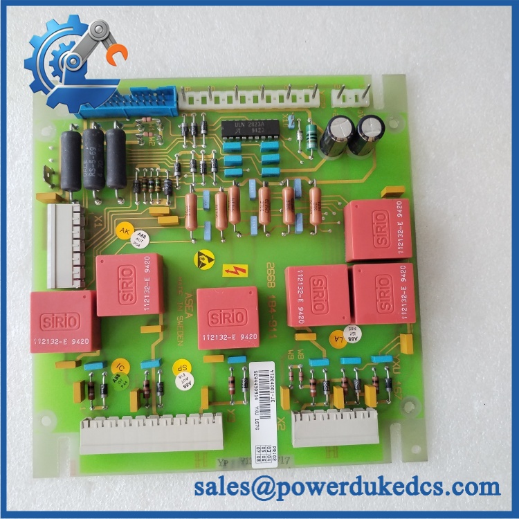
ABB YXU167G YT204001-JE
Module 5: Quality Assurance & Testing SOP
The ABB / should be tested as an isolated pulse-transfer assembly, not merely powered on.
- Identity verification: Record , , serial information, revision markings, and source-board identification.
- OEM anti-counterfeit visual inspection: Examine labels, PCB markings, transformer construction, connector geometry, component layout, and manufacturing identifiers.
- Mechanical inspection: Check the transformer body, PCB, mounting points, connector pins, solder joints, and insulation barriers for damage or contamination.
- Power-on self-test (POST): Install the assembly in an approved low-energy test environment and verify normal startup of the associated control electronics.
- Continuity verification: Check the permitted electrical paths according to the schematic without shorting isolated primary and secondary circuits together.
- Isolation verification: Perform the approved insulation/isolation test using the voltage and limits specified for the particular control assembly.
- Pulse-input simulation: Apply a controlled representative pulse signal to the input side and monitor the corresponding output response.
- Pulse-output verification: Confirm correct pulse presence, timing, amplitude, and waveform on the receiving side using appropriate isolated measurement equipment.
- Repetition test: Exercise the pulse path repeatedly to expose intermittent transformer connections or unstable solder joints.
- Thermal observation: Run the assembly under representative operating conditions and monitor for abnormal temperature rise.
- Extended runtime test: Check for pulse distortion, intermittent loss, or degradation during sustained operation.
- Final QC record: Retain identification photographs, waveform captures, isolation-test results, test date, technician sign-off, and final pass/fail disposition.
The available product references specifically identify as a pulse transformer unit, which is the basis for this test sequence.
Module 6: Maintenance & Reliability FAQ
1. Is ABB a direct replacement, or does it require a firmware flash?
A firmware flash is not normally associated with a pulse-transformer unit. The key compatibility checks are the complete / designation, physical mounting, connector pinout, transformer interface, and the surrounding control hardware. Verify the machine drawing before installation.
2. Is it safe to hot-swap while the system is running?
No. Do not assume live replacement is permissible. A pulse-transformer assembly can be directly associated with power-device triggering, so removing it while the control circuit is energized may interrupt switching commands and create hazardous operating conditions. Use the approved shutdown and isolation procedure.
3. Will replacing cause my current control program to be lost?
The is identified as a pulse transformer unit, not a programmable controller or application-memory device.Replacing it should therefore not erase the main control program. Still, back up the associated controller configuration and record the original wiring before maintenance.
4. What should I verify after installing ?
Verify connector orientation, isolation integrity, control-pulse transfer, waveform quality, and the associated converter diagnostics. A basic continuity check does not prove transformer performance; the receiving-side pulse waveform must be validated under the approved test conditions.
5. What are the warranty terms if the unit fails post-installation?
Warranty should follow the commercial terms for the supplied unit and condition. Retain the serial number, pre-shipment test results, installation date, waveform test records, isolation measurements, and commissioning results. These records help distinguish a defective transformer assembly from a failed driver circuit, damaged connector, incorrect wiring, or a downstream power-stage problem.











 Start Chat


