

Description
- Brand: ALSTOM
- Full Model Number: 3EST125-975 DCC2382A
- System/Series Family: ALSTOM industrial drive/control equipment — exact host system requires nameplate verification
- One-Sentence Core Function: Drive/control interface assembly identified in industrial inventory records as a DCC2382A control unit or control board
- Top 3 Hardcore Specs: DCC2382A control designation; 3EST125-975 assembly reference; application-specific electrical configuration
- Stock Status: New Surplus / Fully Tested Refurbished — verify OEM label, host equipment, and complete electrical configuration before shipment
Module 3: Technical Product Introduction
A control-board replacement becomes risky when a secondary listing supplies specifications that do not agree with the physical assembly. The ALSTOM 3EST125-975 DCC2382A is consistently referenced online as a control unit or control board, with several industrial suppliers describing it as a drive-control component. However, the available public records conflict significantly on its actual application and electrical ratings. One listing describes a drive-control unit with 380–480 VAC input and 250 A maximum output current, while another describes a much larger 690 VAC, 200 A, 150 kW assembly. Neither specification set is sufficiently corroborated by primary ALSTOM documentation.
For procurement, the exact physical identification therefore matters more than generic web specifications. The 3EST125-975 and DCC2382A designations should be retained together, and the complete assembly label should be matched against the customer’s equipment documentation before installation. Some secondary records even classify the same designation as a blue switch-insert or transmission-interface component, further demonstrating that model-only cataloging can produce a false technical description.
Module 4: Application Scenarios & Field Realities
- During replacement of an installed ALSTOM control assembly, start with the removed unit’s nameplate and connector layout. The public record supports the DCC2382A designation, but not one consistent electrical specification set; the host machine or cabinet documentation should determine the actual application.
- When a drive or control system fails to initialize, inspect the module’s power feed, backplane or harness connections, status indicators, and associated control electronics before replacing downstream components. A control-board fault can present as a system-level communication or drive-startup problem.
- For brownfield spare inventory, store as one complete stock identity rather than separating the two designations. Several current records use the same strings while assigning different product categories.
- When an engineering team is migrating an older drive/control cabinet, do not assume this board is a universal 24 VDC or Modbus controller. One commercial page claims 24 VDC and RS-485/Modbus RTU, while another describes 380–480 VAC and 250 A output; those conflicting claims should be treated as unverified until the actual assembly is identified.
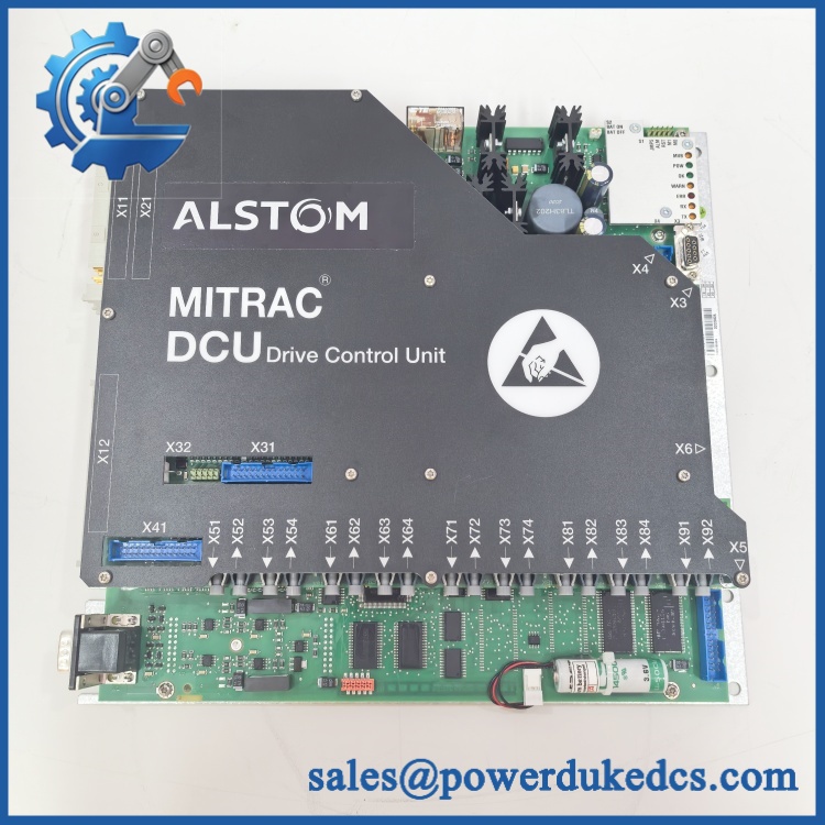
ALSTOM 3EST125-975 DCC2382A
Module 5: Migration, Compatibility & Installation Traps
Replacement Matrix
| Replacement Type | Assessment |
|---|---|
| Drop-in Replacement | Conditional — exact replacement only after host-system, connector, hardware revision, and electrical configuration are confirmed |
| Software Compatible | Unknown — verify controller firmware, parameter set, application configuration, and communication architecture |
| Hardware Modification Required | Unknown — depends on the confirmed application and mating equipment |
⚠️ Field Traps — Watch Out
1. Conflicting electrical specifications.
Current supplier records give materially different ratings for the same designation. Values such as 690 VAC / 200 A / 150 kW and 380–480 VAC / 250 A should not be treated as interchangeable facts.
2. Confirm whether the item is a board, control unit, or complete assembly.
Some records describe it as a drive control unit, while others call it a control board or switch-insert component. The physical packaging and connector arrangement should establish what the customer is actually purchasing.
3. Do not assume ABB specifications apply.
Several commercial pages incorrectly or loosely associate this designation with ABB, even though the supplied brand is ALSTOM. Keep the OEM attribution tied to the actual nameplate and project documentation.
4. Verify all high-voltage interfaces before testing.
Because some published records assign hazardous voltage and high-current ratings to this designation, laboratory energization should not proceed until the actual electrical identity and test procedure are confirmed.
Module 6: Quality Assurance SOP
- OEM anti-counterfeit visual inspection — inspect ALSTOM identification, marking, 3EST125-975 reference, serial information, PCB/assembly labels, connectors, housing, and manufacturing identifiers.
- Exact part-number verification — confirm character-for-character against the purchase order and physical item.
- Application verification — identify the actual host equipment, cabinet, drive, or control system from the customer’s BOM and removed assembly.
- Configuration reconciliation — compare all visible voltage, current, revision, connector, and assembly codes against the approved equipment documentation. Do not import specifications from an unrelated listing.
- Mechanical inspection — examine connectors, mounting hardware, PCB surfaces, terminal interfaces, cooling components, and enclosure surfaces for corrosion, contamination, cracking, impact, or bent contacts.
- Power-on self-test (POST) — energize only after the applicable OEM electrical requirements have been confirmed. Record startup status, diagnostic indications, current behavior, and temperature rise.
- Control-interface verification — validate the actual interface function against the confirmed host equipment using an approved test fixture.
- Input/output verification — test only the verified signal interfaces. Record applied values, measured values, channel or terminal identification, and diagnostic response.
- Parameter/firmware verification — capture firmware, hardware revision, configuration parameters, and stored identification data where applicable.
- Communication handshake verification — perform the applicable interface test only after the communications protocol has been confirmed from the actual equipment documentation. Do not assume Modbus RTU or another protocol from a third-party listing alone.
- System-level validation — install the unit in an approved test environment and confirm expected interaction with the host control or drive system before releasing it for field installation.
- Final QC and packaging — record exact identification, revision information, test results, inspection photographs, ESD protection, and packaging condition before shipment.
Engineering note: The supplied ALSTOM 3EST125-975 can be reliably identified as a -related industrial control assembly, but the currently available public sources disagree on its exact product category and electrical specifications. For a safety- or drive-critical spare, the physical nameplate, host-system BOM, wiring diagram, and OEM documentation should take precedence over third-party voltage, current, power, dimensions, and protocol claims.











 Start Chat


