

Description
- Brand: ALSTOM
- Full Model Number: AL129A CD101152
- System/Series Family: ALSTOM CE2000 / related CE-series control systems
- Core Function: AC-input chopper converter providing isolated low-voltage DC rails for controller and I/O electronics
- Top 3 Hardcore Specs: 96–253 VAC input; 5 VDC / 10 A output; 12 VDC / 4 A output
- Typical Power Rating: Approx. 120 W
- Switching Frequency: Approx. 60 kHz
- Output Type: Galvanically isolated DC outputs
- Compatible Rack References: AM163, AM164, AM166
- Backplane: FB178
- Protection: Overcurrent, overvoltage, and overtemperature protection reported in available technical references
- Operating Temperature: Approx. -20°C to +60°C
- Stock Status: New Surplus or Fully Tested Refurbished; exact revision to be confirmed
Available product references consistently identify AL129A CD101152 as an ALSTOM power supply / chopper converter module associated with CE2000 control hardware, rather than a CPU motherboard.
Module 3: Technical Product Introduction
A control rack can show several apparently unrelated failures when its primary DC supply begins to deteriorate. The ALSTOM AL129A CD101152 is a chopper-converter power module used to generate isolated low-voltage DC rails for ALSTOM control-system electronics. Available technical references associate it with CE2000 equipment and identify compatibility with AM163, AM164, and AM166 racks using the FB178 backplane. The module should therefore be treated as a rack power component, not as a processor or active control CPU.
Its electrical specification is centered on a wide 96–253 VAC input range, with isolated outputs of 5 VDC at up to 10 A and 12 VDC at up to 4 A. The combined power capability is reported at approximately 120 W, with a switching frequency around 60 kHz. Available references also report overcurrent, overvoltage, and overtemperature protection, with an operating range around -20°C to +60°C. Exact output regulation, ripple, hold-up time, and connector pin assignments should be confirmed from the equipment documentation for the specific hardware revision rather than inferred from a generic AL129A listing.
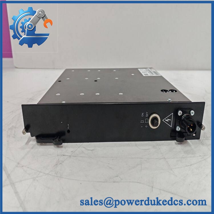
ALSTOM AL129A CD101152
Module 4: Application Scenarios & Field Realities
- Inside an ALSTOM CE2000 controller rack, AL129A provides the low-voltage DC rails required by the installed electronic boards. When several cards suddenly report faults at the same time, measuring the rack DC supply under load should be one of the first diagnostic steps.
- For AM163, AM164, or AM166 rack installations, the FB178 backplane is part of the replacement equation. A module with the correct AC input and DC output ratings can still be unsuitable if its backplane interface or mechanical configuration does not match the installed rack
- During turbine or power-control cabinet refurbishment, the wide 96–253 VAC input range provides tolerance for different AC supply conditions, but it does not remove the need to verify the actual cabinet supply, protective devices, and wiring. An unstable upstream source can be mistaken for a converter failure.
- When investigating intermittent resets on legacy controller electronics, check both 5 V and 12 V rails independently. A marginal output may remain within tolerance with no load yet fall outside the required range once the rack is populated (particularly after years of capacitor aging).
Module 5: Migration, Compatibility & Installation Traps
Replacement Matrix
Replacement classification: Drop-in Replacement when the existing cabinet specifically uses AL129A CD101152 and the replacement matches the same rack, connector arrangement, hardware revision, input-voltage class, and output configuration.
Software compatibility: Not applicable. is a power-conversion module and does not normally require application firmware, PLC logic, or configuration downloads.
Cross-model replacement: Hardware verification required. Other ALSTOM power modules may share similar mechanical formats while providing different input ranges, output rails, current ratings, or backplane arrangements. Nominal 5 V output alone is not sufficient to establish compatibility.
Field Traps — Watch Out
1. Verify the complete input range before energizing. CD101152 is reported for 96–253 VAC input. Do not assume every -family device has the same mains-input capability; the complete nameplate and cabinet documentation should control the replacement decision.
2. Check both output rails under load. The documented output combination is 5 VDC at up to 10 A and 12 VDC at up to 4 A. A 5 V measurement alone does not qualify the supply if the rack also depends on the 12 V rail.
3. Verify rack and backplane compatibility. Available references associate the module with AM163, AM164, AM166, and FB178 hardware. Confirm the exact rack before installation rather than assuming that every CE2000 chassis accepts the same power unit.
4. Do not treat “120 W” as unlimited simultaneous output. The reported 120 W figure describes the overall power capability; the individual 5 V and 12 V current limits still apply. The actual load must be calculated from both rails and the cabinet’s distribution architecture.
5. Watch for thermal conditions. A supply that passes a short bench test can still fail after the cabinet reaches operating temperature. Monitor output regulation and temperature during an extended loaded test — especially for older surplus units.
Module 6: Quality Assurance SOP
Pre-Shipment Inspection Protocol for ALSTOM CD101152
- OEM identity inspection: Verify ALSTOM marking, designation, part number, serial number, hardware revision, and all visible nameplate data.
- Variant verification: Confirm that the unit corresponds specifically to the required configuration and not a similar ALSTOM power-conversion assembly.
- Mechanical inspection: Examine the enclosure, mounting hardware, captive screws, connectors, insulating barriers, heat-dissipation surfaces, and backplane interface for deformation, corrosion, contamination, or unauthorized modification.
- Connector inspection: Check AC-input and DC-output/backplane contacts for oxidation, bent contacts, damaged housings, contamination, and signs of overheating.
- Component inspection: Inspect capacitors, inductors, transformers, semiconductors, heat sinks, solder joints, and protective components for leakage, cracking, discoloration, or previous repair activity.
- Power-input verification: Confirm the intended 96–253 VAC test source and polarity/connection arrangement from the applicable ALSTOM documentation before energizing the module.
- Power-on test: Energize the unit through an appropriately protected laboratory supply and monitor startup current, abnormal noise, switching instability, odor, and temperature rise.
- 5 VDC output test: Measure the 5 VDC rail at no load and representative load conditions, recording output voltage stability and current capability up to the applicable 10 A limit.
- 12 VDC output test: Perform the same verification on the 12 VDC rail, using representative loading up to the applicable 4 A limit.
- Combined-load test: Apply representative simultaneous 5 V and 12 V loading to verify stable operation of the complete converter rather than testing each output independently.
- Load-regulation test: Record output voltage at incremental load points and identify any excessive droop, ripple, oscillation, or intermittent regulation.
- Protection verification: Where the laboratory procedure permits, evaluate controlled overcurrent, overload, and thermal-protection behavior without exceeding approved test limits.
- Backplane interface test: Install the unit in a compatible ALSTOM rack or laboratory fixture and verify correct mechanical seating and DC-rail distribution through the intended interface.
- Rack-level power test: With representative CE2000 electronics installed, confirm that the maintains both output rails under realistic cabinet loading.
- Thermal soak: Operate the converter under representative combined load for an extended period and monitor output stability, component temperature, and protection behavior.
- Fault recovery test: Where permitted by the approved test procedure, cycle the AC input and verify controlled restart without abnormal output overshoot or repeated startup oscillation.
- Final QC record: Record exact model, identifier, revision, serial number, input voltage, 5 V measurements, 12 V measurements, combined load, protection observations, thermal results, test duration, and inspector approval.
- ESD and mechanical packaging: Protect the connectors, mounting interfaces, enclosure, and heat-dissipation surfaces against impact, moisture, contamination, and electrostatic discharge during shipment.
Procurement note: The technically supported identification is ALSTOM — CE-series chopper converter power supply module. Available technical references consistently associate it with 96–253 VAC input, isolated 5 VDC / 10 A and 12 VDC / 4 A outputs, approximately 120 W total capability, and AM163/AM164/AM166 rack installations using the FB178 backplane. Public reseller descriptions sometimes mislabel this unit as a CPU board, so the physical nameplate and complete rack documentation should take priority during asset registration and replacement qualification.











 Start Chat


