

Description
- Brand: ALSTOM / Converteam
- Full Model Number: DX21-M2
- System/Series Family: ALSTOM Microtech Digital Excitation System
- One-Sentence Core Function: Microprocessor-based digital excitation controller providing AVR and excitation control for synchronous generators and motors
- Top 3 Hardcore Specs: 100–120 VAC VT sensing; 1 A secondary CT input; BS7625 Class 1 measurement accuracy
- Stock Status: Stock condition and exact hardware revision to be confirmed
Module 3: Technical Product Introduction
Generator voltage instability is not always caused by the power stage. A failed excitation controller can disrupt automatic voltage regulation, reactive-power control, excitation limiting, and the transfer between automatic and manual operating modes. The ALSTOM DX21-M2 is a Microtech digital excitation controller designed for excitation systems serving synchronous generators and motors. Its control architecture combines generator sensing, excitation regulation, limiting functions, operator diagnostics, and configurable control modes in one dedicated controller. Current industrial references identify the DX21-M2 as a discontinued digital excitation controller from the ALSTOM/Converteam Microtech family.
The published electrical data identifies 100–120 VAC VT sensing at 50/60 Hz, with approximately 1 VA per phase and zero phase shift, together with a 1 A secondary compounding CT input and approximately 1 VA CT burden. Measurement accuracy is specified to BS7625 Class 1. Available product references also associate the controller with excitation-current capability of up to approximately 15 A continuous and 35 A transient forcing current, although those output figures should be verified against the exact excitation-system configuration before being used as installation limits.
Module 4: Application Scenarios & Field Realities
- On synchronous generators, the DX21-M2 provides the excitation-control layer required to maintain generator terminal voltage under changing load conditions. During troubleshooting, check VT sensing, CT input, excitation power stage, and controller feedback together; a voltage-regulation fault does not automatically indicate a defective DX21-M2.
- For generators operating with reactive-power or power-factor control, the controller can regulate excitation in response to the selected control objective. The configuration should be preserved during replacement because changing the control mode or limiting parameters can materially affect generator operating behavior.
- Where excitation systems use automatic and manual operating modes, the transfer logic deserves attention during commissioning. The controller includes trip-to-manual functionality and excitation limiting, so a replacement should be tested for correct mode transition rather than validated only by checking the measured generator voltage.
- During maintenance of older Microtech excitation cabinets, retain the complete DX21-M2 identification and parameter record. Available references identify the unit as discontinued, which makes exact hardware and configuration matching especially important when supporting an aging generator excitation installation.
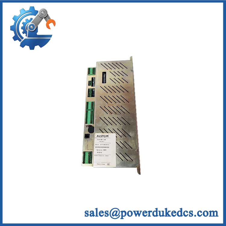
ALSTOM DX21-M2
Module 5: Migration, Compatibility & Installation Traps
Replacement Matrix
Replacement Classification: Configuration-Matched Replacement — Excitation-System Parameters Must Match
A like-for-like replacement is appropriate when the installed excitation system uses the same Microtech controller architecture, sensing arrangement, firmware/configuration baseline, and associated power electronics. The controller should not be treated as an independent generic AVR because its behavior depends on the generator ratings, VT/CT ratios, excitation hardware, and configured control limits.
→ Different Microtech controller: Software and Hardware Modification Required. A newer or different controller may provide equivalent excitation functions while using different I/O interfaces, parameter structures, firmware, and commissioning procedures.
→ Generic AVR: Hardware Modification Required. A generic AVR cannot be assumed to reproduce the original excitation-control logic, limiter characteristics, manual-transfer behavior, sensing interface, or field wiring.
⚠️ Field Traps — Watch Out
1. VT ratio and sensing configuration: The uses generator voltage-transformer sensing. Verify the actual VT secondary voltage, frequency, phase arrangement, burden, and scaling parameters before commissioning the replacement. A controller with incorrect VT configuration can regulate to the wrong voltage even though the sensing circuit appears electrically healthy.
2. CT polarity and ratio: The compounding CT input is specified for a 1 A secondary. CT polarity and phase relationship are critical; an incorrect CT orientation can cause abnormal excitation response or incorrect reactive-load compensation.
3. Excitation-current capability: Published secondary references cite approximately 15 A continuous and 35 A transient forcing current, but the actual excitation-system current path may involve separate power components. Confirm which values apply to the complete system rather than assuming they are direct controller output ratings.
4. Parameter retention: Generator voltage setpoints, droop, reactive-power settings, limiter thresholds, V/Hz limits, and manual-mode parameters should be documented before replacement. A physically identical controller with an incorrect parameter set is not a functional replacement.
Module 6: Quality Assurance SOP
Each ALSTOM should undergo a documented controller, sensing, configuration, and functional test before shipment.
- OEM identification visual inspection: Verify ALSTOM / Converteam / Microtech markings, designation, serial number, hardware revision, front-panel labels, connectors, display, switches, and visible PCB identification.
- Configuration capture: Record the complete hardware revision and, where accessible, all programmed excitation parameters before removing the existing controller.
- Mechanical inspection: Examine the enclosure, PCB, connectors, terminal points, mounting hardware, display, selector switches, and accessible components for impact, corrosion, contamination, overheating, or evidence of previous repair.
- VT input verification: Apply a controlled three-phase VT simulation corresponding to the documented 100–120 VAC sensing range and verify correct voltage and frequency measurement behavior.
- Frequency verification: Test representative 50 Hz and 60 Hz conditions and confirm correct controller measurement and operating response.
- CT input simulation: Apply a calibrated 1 A secondary current signal at the appropriate input and verify correct magnitude and phase interpretation.
- Measurement accuracy test: Compare voltage and current measurements with calibrated references and verify the applicable BS7625 Class 1 performance requirement.
- Power-on self-test (POST): Confirm normal controller initialization, display operation, status LEDs, alarm indications, and diagnostic behavior.
- AVR functional test: Use an approved excitation-system simulator or closed-loop laboratory setup to verify automatic voltage regulation response.
- Manual-mode verification: Confirm correct transfer between automatic and manual excitation modes and verify that the configured control variable remains within the approved range.
- Reactive-power/PF control test: Where enabled by the project configuration, simulate representative reactive-power or power-factor conditions and verify the expected control response.
- Limiter verification: Exercise authorized OEL, UEL, V/Hz, stator-current, and excitation-limit functions using controlled simulator inputs. Do not test protection functions by forcing a live generator outside approved operating limits.
- Trip-to-manual test: Verify the documented transfer logic and confirm that the expected manual mode is established following the approved trip or fault condition.
- Communication/diagnostic test: Where the installed configuration provides a computer or serial interface, verify diagnostic communication and parameter access using the approved maintenance procedure.
- Excitation-response stability test: Run representative voltage-reference changes and load changes while monitoring controller output, simulated generator response, limiter status, and diagnostic alarms.
- Extended stability test: Operate the controller continuously under simulated excitation-system conditions while monitoring sensing stability, control response, alarms, and temperature.
- Final QC record: Retain identification photographs, hardware revision, VT/CT test results, accuracy measurements, AVR response data, limiter-test results, mode-transfer results, communication observations, configuration records, and final QC approval.
The is a Microtech digital excitation controller / AVR for synchronous-machine excitation systems. The available specifications identify 100–120 VAC VT sensing, 1 A secondary CT input, 50/60 Hz operation, approximately 1 VA sensing burden, BS7625 Class 1 accuracy, and published excitation-control capability associated with automatic voltage regulation, reactive-power and power-factor control, excitation limiting, and manual-transfer functions.
For spare-parts control, the critical replacement attributes are the hardware revision, VT and CT ratios, phase configuration, excitation-system architecture, programmed control parameters, limiter settings, manual-transfer logic, and associated power-stage compatibility. Because the is a legacy/discontinued controller, exact configuration matching should be completed before a warehouse spare is released for generator service.











 Start Chat


