

Description
- Brand: ALSTOM
- Full Model Number: EPSD-0603 / DFI-150-0003
- System/Series Family: ALSTOM boiler and combustion flame-monitoring system / LIMELIGHT
- One-Sentence Core Function: Flame-monitoring and diagnostic assembly used to process combustion-sensor signals and provide flame-status information
- Top 3 Hardcore Specs: EPSD-0603 flame-monitoring controller; DFI-150-0003 LIMELIGHT diagnostic board; digital flame-status indication
- Stock Status: Stock condition and exact assembly revision to be confirmed
Module 3: Technical Product Introduction
A flame-monitoring fault is a safety concern, not simply an instrumentation inconvenience. The ALSTOM EPSD-0603 is identified in available industrial references as a flame-monitoring control unit used with the DFI-150-0003 flame-indicator/diagnostic board. The EPSD-0603 is associated with combustion safety applications, while DFI-150-0003 is described as a LIMELIGHT diagnostic circuit board with digital readout and flame indication. Together, the hardware is used to process and display flame-condition information within legacy combustion-monitoring installations.
The exact electrical configuration should be treated carefully because the public documentation available for this combined identification is limited. Current references agree on the flame-monitoring role of the EPSD-0603 and the diagnostic/display function of DFI-150-0003, but detailed OEM-level data for every signal interface, sensor type, timing parameter, and output rating is not consistently published. One supplier reference describes a 24 VDC control supply and multiple analog and relay interfaces, while the DFI-150-0003 references identify the board as a LIMELIGHT flame indicator/diagnostic PCB. Those details should therefore be validated against the physical nameplate, cabinet drawings, and original system documentation before being used as certified installation specifications.
Module 4: Application Scenarios & Field Realities
- On thermal-power boiler burner systems, the EPSD-0603/ combination is relevant where flame presence must be evaluated before fuel admission or maintained combustion. A replacement should be checked against the installed burner-management architecture, including the flame sensor type and the associated trip logic.
- For gas-fired or oil-fired combustion equipment, the provides the local flame indication and diagnostic function identified in current product references. During troubleshooting, compare the displayed flame condition with the sensor signal and the external interlock status instead of assuming that a missing flame indication proves the detector itself has failed.
- Within legacy Alstom combustion-control cabinets, the exact relationship between and matters. The controller and diagnostic board should be treated as related components of the flame-monitoring chain rather than as two interchangeable board numbers. Verify connector pinout, board revision, and cabinet position before removal.
- During emergency spare replacement, preserve the existing parameter settings and wiring records. Flame-protection systems can generate a normal-looking diagnostic display even when the sensor interface, signal conditioning, or downstream trip circuit is incorrect, so a complete functional test is preferable to a visual inspection alone.
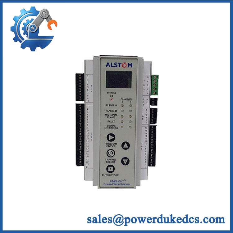
ALSTOM EPSD-0603 DFI-150-0003
Module 5: Migration, Compatibility & Installation Traps
Replacement Matrix
Replacement Classification: Configuration-Matched Replacement — Verify Complete Assembly Before Installation
The / combination should be treated as a configuration-specific flame-monitoring assembly. Available references associate with the flame-monitoring control function and with the LIMELIGHT flame-indicator/diagnostic circuit board. A direct replacement is appropriate only when the replacement hardware matches the installed cabinet architecture, connector arrangement, sensor interface, and board revision.
→ generic flame-indicator board: Hardware Modification Required. The is a specific LIMELIGHT diagnostic PCB. Similar display or flame-monitoring boards should not be assumed electrically interchangeable.
→ another flame-monitoring controller: Hardware Modification Required. Different flame-monitoring systems can use different sensor interfaces, logic outputs, timing, and trip behavior. A generic replacement should not be treated as a drop-in substitute without documented compatibility.
⚠️ Field Traps — Watch Out
1. Controller versus diagnostic-board identity: and should remain separate inventory identifiers. One is associated with the flame-monitoring control assembly, while is identified as a LIMELIGHT diagnostic/display PCB.
2. Sensor-interface mismatch: Flame-monitoring equipment can use different sensing technologies and signal-conditioning arrangements. Verify the installed detector type, input wiring, and signal polarity before connecting a replacement.
3. Trip-logic verification: Do not validate the replacement solely by confirming that the digital display or flame indicator illuminates. The complete chain—from detector input through signal processing to the external fuel/interlock circuit—should be functionally verified.
4. Unverified published ratings: Public supplier pages contain conflicting technical values for . Treat generic voltage, current, communication, and response-time claims as preliminary until the exact hardware revision and OEM documentation are confirmed.
Module 6: Quality Assurance SOP
Each ALSTOM / assembly should undergo a controlled identification and functional inspection before shipment.
- OEM identification visual inspection: Verify ALSTOM markings, , , serial numbers, board revision, LIMELIGHT markings, connectors, and visible assembly identifiers.
- Assembly relationship verification: Record the controller and diagnostic-board identifiers separately and document how they are installed in the original cabinet.
- Mechanical inspection: Examine PCBs, connectors, terminal blocks, mounting hardware, display components, cable interfaces, and housings for impact, corrosion, contamination, or evidence of previous repair.
- Nameplate and revision capture: Photograph all identification labels before testing. Record every visible revision and suffix.
- Power verification: Apply only the supply specified for the exact hardware revision using an approved laboratory setup. Do not rely on an unverified third-party voltage rating.
- Power-on self-test (POST): Confirm normal startup behavior, display initialization, status indicators, and diagnostic response.
- Flame-signal simulation: Use an approved flame-detector simulator or equivalent test fixture to reproduce the documented sensor signal and verify correct recognition by the monitoring chain.
- Flame-presence verification: Confirm the expected flame-present indication and verify that the displayed diagnostic state follows the simulated input.
- Flame-loss verification: Apply the approved flame-loss condition and confirm the expected diagnostic indication and downstream protective response.
- Digital display test: Verify that the diagnostic/display function responds correctly and that all applicable displayed states can be reproduced under controlled conditions.
- Diagnostic-function test: Exercise authorized sensor-fault and internal-diagnostic conditions and confirm correct fault reporting.
- Output/interlock verification: Test the applicable relay or discrete outputs using a safe laboratory load and verify the expected state transitions without connecting production fuel equipment.
- Communication verification: Where the installed revision provides an external communication interface, verify the configured communication path against the original cabinet documentation.
- Extended stability test: Operate the assembly continuously with simulated flame-status changes while monitoring diagnostic state, display behavior, supply stability, and output consistency.
- Final QC record: Retain identification photographs, hardware revisions, sensor-simulation results, display results, diagnostic results, output tests, communication observations where applicable, and final QC approval.
The ALSTOM / combination is best identified as a legacy flame-monitoring and diagnostic assembly, with associated with flame-monitoring control and identified as a LIMELIGHT flame-indicator/diagnostic circuit board with digital readout.
For spare-parts control, retain the full and identifiers, confirm the physical revision and cabinet wiring, and validate the complete flame-sensing and interlock chain before installation. Because publicly available specifications are inconsistent, unverified voltage, current, timing, and communication figures should not be presented as fixed purchasing specifications without documentation for the exact unit.











 Start Chat


