

Description
- Brand Alstom / GE Grid Solutions legacy
- Full Model Number EPSD-0603
- System/Series Family Alstom power protection / digital fault indication equipment
- Core Function Digital fault indication and associated protection-system signal processing
- Top 3 Hardcore Specs EPSD-0603 assembly | Associated DFI-150-0003 references reported | Application-specific protection equipment
- Stock Status New Surplus — exact subassembly, revision, voltage, and application must be verified from the physical nameplate before shipment
Module 3: Technical Product Introduction
A protection-system replacement cannot be selected reliably from a generic description alone. The Alstom EPSD-0603 designation appears in multiple secondary catalogs with conflicting classifications. The strongest current product references associate EPSD-0603 with digital fault indication equipment, including an EPSD-0603 DFI-150-0003 assembly intended for power-distribution fault detection. Other listings classify the same EPSD-0603 designation as a flame-monitoring control module or a generic controller board. Because these descriptions conflict materially, the exact physical assembly and its companion part number should be confirmed before a replacement is approved.
For procurement purposes, should therefore be treated as an application-specific Alstom assembly, not as a generic power-supply or PLC card. One current reference associates the unit with DFI-150-0003 digital fault indication, while another Alstom spare-parts catalog lists under digital fault indication products. Alstom’s present customer portal also provides dedicated spare-parts and obsolescence support for legacy equipment. Exact operating voltage, communications interface, dimensions, current draw, and environmental ratings should be taken from the physical unit or controlled project documentation rather than inferred from inconsistent secondary listings.
Module 4: Application Scenarios & Field Realities
- In power-distribution fault monitoring, the designation is associated with DFI-150-0003 digital fault-indication equipment. Reported functions include detection of phase-to-phase and phase-to-ground faults, with the complete DFI assembly intended for medium-voltage distribution monitoring.
- Where a protection cabinet contains several application-specific boards, the exact subassembly matters. A card identified only as “” may belong to a larger assembly, so the mating equipment, connector arrangement, and board revision should be recorded before removal.
- During legacy Alstom equipment maintenance, avoid replacing the unit solely from a supplier database description. Current search results show materially different functions under the same model designation, which is a clear indication that the physical identification and project BOM should control the replacement decision.
- For urgent protection-system recovery, photograph the PCB label, connector side, revision markings, and any companion model number such as DFI-150-0003. That additional evidence can distinguish the intended application before a spare is dispatched.
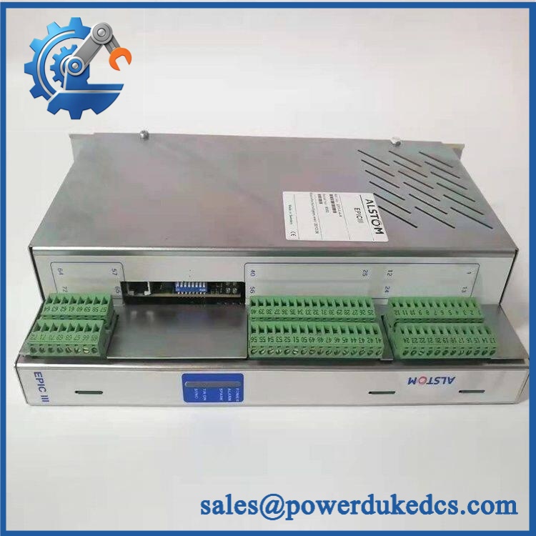
Alstom EPSD-0603
Module 5: Migration, Compatibility & Installation Traps
Replacement Matrix
| Replacement Status | Engineering Assessment |
|---|---|
| Drop-in Replacement | Potentially yes, but only after confirming the exact subassembly, revision, companion equipment, connector arrangement, and application. |
| Software Compatible | Not established from the available evidence. Confirm whether the particular assembly contains configurable logic, firmware, or only application-specific electronics. |
| Hardware Modification Required | Unknown until the exact physical assembly and mating system are confirmed. Do not authorize modification based on the base model alone. |
⚠️ Field Traps: Watch Out
The designation is not sufficiently specific by itself. Current sources associate it with digital fault indication equipment, while another supplier identifies as a flame-monitoring control module with completely different electrical and process functions. This level of conflict makes physical identification mandatory.
Do not infer the voltage specification from secondary listings. One supplier page reports a 24 VDC supply for its flame-monitoring product, while the DFI-150-0003 listing describes a medium-voltage fault-indication system. These are not compatible assumptions.
Check the companion model number. The notation appears directly alongside in digital-fault-indicator references. When that identifier is present on the physical assembly, retain it in the procurement record.
Do not treat as a generic communication controller. Several secondary pages assign IEC 61850, CAN bus, or other interfaces to the designation without providing a controlled Alstom source that confirms those specifications. Those claims should not be used for engineering substitution.
Module 6: Quality Assurance SOP
Because the public documentation for is inconsistent, the QA process should begin with identity verification before electrical testing.
- OEM anti-counterfeit visual inspection: Verify Alstom markings, exact designation, PCB identification, revision, labels, connector arrangement, component layout, and any companion designation such as .
- Part-number and traceability check: Record all model numbers, revisions, serial numbers, date codes, manufacturing labels, and assembly references found on the physical unit.
- Application identification: Match the physical module against the customer’s BOM, cabinet drawing, equipment model, and removed-unit photographs before energization.
- Mechanical inspection: Check PCB surfaces, connectors, mounting hardware, terminal areas, enclosure condition, and accessible components for corrosion, contamination, bent contacts, impact damage, or unauthorized rework.
- Connector verification: Compare connector keying, pin count, contact arrangement, and mating hardware with the original assembly.
- Power-input verification: Determine the approved supply voltage from the controlled documentation for the exact revision before applying laboratory power. Do not use an assumed 24 VDC source.
- Power-on self-test (POST): Where the assembly documentation defines startup diagnostics, perform the approved power-up sequence and record all LEDs, alarms, and fault states.
- Functional I/O verification: Test each documented input and output using the applicable controlled test fixture for the identified application.
- Digital fault-indication verification: Where the unit is confirmed as part of the architecture, simulate the approved fault inputs and verify correct fault detection, indication, and reset behavior.
- Protection-interface verification: Confirm the module correctly exchanges status with the associated protection equipment and that no unintended trip or alarm condition is generated during normal operation.
- Communication handshake verification: Perform only the protocol test documented for the exact assembly. Do not assume Ethernet, IEC 61850, CAN, RS-485, or another interface solely from third-party product descriptions.
- Diagnostic verification: Apply controlled abnormal conditions permitted by the relevant Alstom procedure and confirm that the expected diagnostic state is generated and cleared correctly.
- Thermal and extended-run test: Operate the confirmed assembly under representative application loading while monitoring supply current, temperature, alarms, resets, and intermittent faults.
- Final QC record: Document the verified application, exact model and revision, companion model number, applied supply, functional-test results, diagnostic behavior, communications where applicable, extended-run observations, traceability, and packing status.
Technical Identification Note: The supplied designation cannot be normalized confidently to one universal function from public sources. Current references associate it with digital fault indication equipment, while another current listing describes an flame-monitoring controller with substantially different specifications. An Alstom parts catalog also lists under digital fault indication. Therefore, the safest procurement description is , with the physical board label, revision, companion equipment number, and application verified before shipment.











 Start Chat


