

Description
-
- Brand: ALSTOM
- Full Model Number: I/OBE2 12004-104-00 V1.0.0
- System/Series Family: ALSTOM remote I/O / SBS control-system architecture
- One-Sentence Core Function: I/O bus extension interface connecting distributed I/O assemblies with the main control system
- Top 3 Hardcore Specs: I/OBE2 bus extension architecture; 12004-104-00 hardware assembly; V1.0.0 revision
- Stock Status: Stock condition and exact hardware revision to be confirmed
Module 3: Technical Product Introduction
When an entire remote I/O section disappears from the controller, replacing individual signal cards rarely solves the actual problem. ALSTOM I/OBE2 12004-104-00 V1.0.0 is an I/O bus extension interface used within legacy ALSTOM distributed-I/O architectures. Its primary function is communication between the main control equipment and a remote I/O assembly, allowing field input and output data to pass through the system bus rather than routing every signal directly to the central cabinet.
The full identification contains three useful purchasing controls: I/OBE2 identifies the board family, 12004-104-00 identifies the hardware assembly, and V1.0.0 identifies the documented revision. Detailed public OEM specifications for this exact assembly are limited, so fixed values for supply tolerance, bus speed, connector pinout, environmental rating, and isolation should be confirmed against the physical board and system documentation before being used as installation specifications. That distinction is important with legacy ALSTOM equipment, where similar board references can perform very different functions.
Module 4: Application Scenarios & Field Realities
- Inside distributed power-plant control cabinets, the I/OBE2 can provide the communication path between the main controller and a remote I/O rack. If an entire remote rack stops updating, inspect the bus interface, cable path, termination, and power distribution before replacing healthy field I/O cards.
- For turbine and auxiliary-system remote I/O, a centralized controller may collect signals from equipment located several meters away. The I/OBE2 supports that distributed arrangement, while the actual bus cable and termination configuration must remain consistent with the installed cabinet design.
- Where analog and digital I/O share one remote assembly, the I/ operates at the bus level rather than processing one individual field signal. A correct replacement should therefore be evaluated by its communication behavior and rack compatibility, not by analog-input or digital-output specifications.
- During emergency maintenance on an older ALSTOM installation, photograph the complete board label before removing the failed unit. The difference between 12004-104-00 and other nearby 12004-series references can be significant, and the V1.0.0 revision should remain part of the warehouse record.
Module 5: Migration, Compatibility & Installation Traps
Replacement Matrix
Replacement Classification: Drop-in Replacement Within the Matching ALSTOM I/O Bus Architecture
A like-for-like I/ 12004-104-00 V1.0.0 replacement is suitable when the existing cabinet uses the same I/ architecture, compatible backplane, remote-I/O rack, bus cabling, termination arrangement, and revision level. A physical board match alone is not sufficient evidence of system compatibility.
I/ → Different 12004-Series Interface Board: Hardware Modification Required. Similar part-number families do not establish identical bus functions, connector assignments, or system positions.
I/ → Generic Remote I/O Module: Hardware Modification Required. The I/ operates as a bus-level interface and cannot be replaced by an ordinary analog or digital I/O card.
⚠️ Field Traps — Watch Out
1. Bus termination mismatch: Incorrect termination or cable topology can prevent communication with the entire remote I/O rack. Recheck the original bus arrangement before energization.
2. Revision mismatch: Preserve the complete V1.0.0 identification when the customer’s installed system requires that revision. A later board revision should not automatically be considered interchangeable.
3. Connector pinout: Never assume that a physically matching connector guarantees identical signal assignment. Verify every connection against the approved cabinet drawing before powering the replacement.
4. Remote-rack fault versus board fault: If all channels on one remote rack disappear simultaneously, first investigate the I/O bus, power, termination, and I/ interface. Multiple simultaneous field-card failures are usually a weaker initial hypothesis.
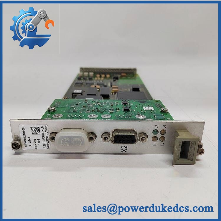
ALSTOM I/OBE2 12004-104-00 V1.0.0
Module 6: Quality Assurance SOP
Each ALSTOM I/ 12004-104-00 V1.0.0 should undergo a documented identification and communication-interface test before shipment.
- OEM identification visual inspection: Verify ALSTOM markings, designation, 12004-104-00 hardware number, V1.0.0 revision, serial number, PCB labels, connectors, and board identification marks.
- Revision capture: Photograph the complete label and record every hardware and firmware designation visible on the board.
- Mechanical inspection: Examine the PCB, edge connectors, mounting points, guides, jumpers or switches, front-panel indicators, and accessible components for cracks, corrosion, contamination, oxidation, or evidence of repair.
- Power verification: Install the board in an approved compatible ALSTOM test rack and apply the documented system supply for the exact hardware revision.
- Power-on self-test (POST): Confirm normal startup, diagnostic indication, and board initialization.
- Bus communication test: Connect the I/ to an approved controller and compatible remote-I/O test assembly and verify stable communication.
- Data-transfer verification: Exercise representative remote inputs and outputs and confirm that the controller receives and transmits the expected data.
- Connector continuity test: Verify the applicable bus conductors and connector contacts against the approved wiring documentation.
- Bus-integrity test: Check communication stability under representative traffic and monitor error counters, communication interruptions, and recovery behavior where the test system provides those diagnostics.
- Termination verification: Confirm the installed bus termination arrangement matches the approved topology. Do not add or remove termination components based only on visual similarity.
- Remote-I/O mapping test: Verify that representative analog and digital channels from the remote rack are correctly mapped to the control system.
- Fault-response test: Simulate an approved bus interruption and verify that the control system reports the expected communication fault.
- Isolation verification: Where required by the applicable engineering specification, perform the approved isolation test using controlled laboratory equipment and protect sensitive electronics from inappropriate test voltage.
- Thermal observation: Run the assembly continuously under representative communication traffic and monitor board temperature, diagnostic status, and communication stability.
- Extended stability test: Maintain sustained I/O data exchange and record any communication errors, unexpected resets, or data-integrity faults.
- Final QC record: Retain identification photographs, revision data, supply measurements, connector checks, communication results, remote-I/O mapping results, fault-response observations, thermal data, and final QC approval.
The ALSTOM I/ 12004-104-00 V1.0.0 should be treated as an I/O bus extension interface, not as a conventional field I/O channel module. Its primary replacement concern is compatibility with the installed distributed-I/O architecture, including the I/ board family, 12004-104-00 hardware identification, V1.0.0 revision, connector assignment, bus topology, termination, and remote-rack configuration.
Because detailed OEM specifications for this exact assembly are not consistently available in public references, fixed electrical and communication parameters should be verified from the physical unit and original ALSTOM documentation before being published as certified purchasing data.











 Start Chat


