

Description
- Brand ALSTOM
- Full Model Number I/OBUS2 12004-103-01 VER:V1.2.0
- System/Series Family ALSTOM Train/Station Control Electronics
- Core Function I/O bus interface between the control processor subsystem and distributed I/O hardware
- Top 3 Hardcore Specs 12004-103-01 hardware designation | V1.2.0 firmware/software version marking | I/O bus interface function
- Stock Status New Surplus — verify hardware revision, firmware version, connector arrangement, and host system before shipment
Module 3: Technical Product Introduction
A failed I/O bus interface can make multiple healthy I/O modules appear unavailable at once. The ALSTOM I/OBUS2 12004-103-01 VER:V1.2.0 is identified in current rail-system certification material as an I/OBUS2 hardware component, with the 12004-103-XX designation belonging to the I/OBUS2 family. In the documented control architecture, I/OBUS2 sits alongside modules such as VLE, VPS, I/OBE2, VIIB16, and VOOB8, indicating that it serves as part of the internal control-system/I/O communication chain rather than as a conventional standalone PLC CPU.
The exact electrical and communication specifications require revision control. Secondary listings describe I/OBUS2 12004-103-01 as an I/O bus interface module, with one source reporting a backplane-powered architecture; other supplier pages publish conflicting claims about voltage, protocols, throughput, and isolation. Those unverified figures should not be treated as OEM specifications. The V1.2.0 version marking itself is important, because the compatible host processor, associated I/O modules, and software baseline should be checked as one system before replacement.
Module 4: Application Scenarios & Field Realities
- Within a rail control electronics cabinet, I/ provides the internal I/O bus interface associated with the distributed I/O architecture. Certification records list I/ as hardware version 12004-103-XX within the station-control processing subsystem.
- Where multiple I/O boards share a common controller, an I/ failure can present as a broad communication or I/O availability problem rather than one isolated channel fault. Before replacing several I/O cards, verify the common bus interface and its connectors.
- During a maintenance replacement involving V1.2.0 hardware, firmware and system version matching deserve priority. A physically identical board with a different software baseline can produce compatibility or initialization faults even when the backplane connection is correct.
- For legacy rail-control equipment, the 12004-103-01 identifier should be preserved exactly in the maintenance record. Current certification evidence confirms the broader I/ 12004-103-XX family, while secondary product pages explicitly identify 12004-103-01 VER:V1.2.0 as an I/O bus interface module.
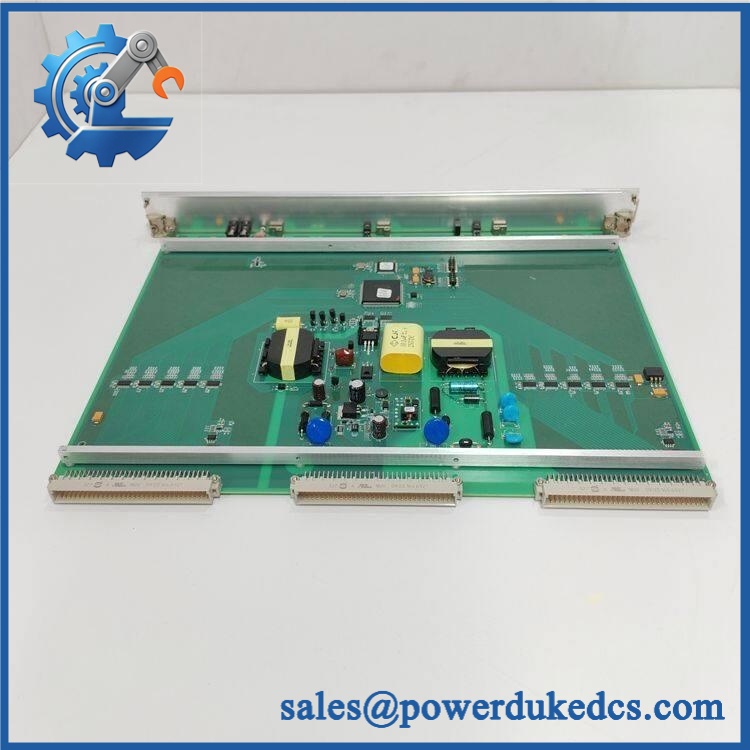
Alstom I/OBUS2 12004-103-01 V1.2.0
Module 5: Migration, Compatibility & Installation Traps
Replacement Matrix
| Replacement Status | Engineering Assessment |
|---|---|
| Drop-in Replacement | Yes, only for a like-for-like I/ 12004-103-01 VER:V1.2.0 installation with the same host controller, backplane, I/O architecture, and approved revision baseline. |
| Software Compatible | Version-dependent. The V1.2.0 marking must match the host system’s approved software/firmware configuration and associated I/O hardware revisions. |
| Hardware Modification Required | Normally no for an exact replacement. Modification may be required when migrating between I/ hardware revisions, control-processor generations, or different I/O bus architectures. |
⚠️ Field Traps: Watch Out
Do not assume every 12004-103-01 listing has the same specifications. Secondary sources report conflicting supply voltages, protocols, memory sizes, and environmental specifications. Use the actual module label and controlled Alstom project documentation as the engineering baseline.
Do not confuse I/ with I/OBE2. Certification records list these as separate hardware families: I/ = 12004-103-XX, while I/OBE2 = 12004-104-XX. Their roles within the control architecture are different.
Preserve the exact version marking. The supplied unit is specifically marked VER:V1.2.0. Firmware or software revision mismatch should be investigated before inserting a spare into a live rail-control chassis.
Check the complete system chain. I/ works as part of a larger control subsystem that may include VLE, VPS, I/OBE2, VIIB16, and VOOB8 modules. A bus-interface replacement should therefore be validated at the system level rather than by testing the board in isolation.
Verify the physical connector and host interface. Public supplier descriptions are inconsistent about whether the module is independently powered or backplane-powered. Do not apply external laboratory voltage until the exact board schematic or maintenance documentation has been established.
Module 6: Quality Assurance SOP
Because I/ is a system-level I/O interface, QA should emphasize revision control, bus integrity, module recognition, and complete system communication.
- OEM anti-counterfeit visual inspection: Verify ALSTOM identification, I/ 12004-103-01 marking, VER:V1.2.0 designation, PCB revision, connector geometry, labels, and component layout against controlled reference material.
- Part-number and traceability check: Record the complete 12004-103-01 designation, hardware revision, software/firmware version, serial number, manufacturing/date codes, and host-system reference.
- Mechanical inspection: Examine the backplane connector, retaining hardware, PCB, enclosure, keying features, and accessible components for bent contacts, corrosion, contamination, cracks, or unauthorized rework.
- Power-interface verification: Determine the correct power path from the applicable controlled documentation before energization. Do not rely on conflicting secondary claims regarding external supply voltage.
- Power-on self-test (POST): Install the board in an approved host-system test configuration and record initialization behavior, status indicators, and any bus or module faults.
- Firmware/version verification: Confirm the installed software or firmware is V1.2.0 where that version is part of the supplied assembly identification, and compare it with the approved host-system baseline.
- I/O bus continuity test: Verify all applicable bus conductors and connector contacts for continuity, insulation, and absence of unintended shorts.
- Bus integrity test: Connect the module to the approved control processor and I/O configuration and verify stable bus operation without intermittent node loss.
- Module-recognition test: Confirm the host controller correctly identifies the I/ interface and recognizes the expected downstream I/O architecture.
- I/O data-transfer test: Exercise representative downstream I/O channels and verify that input and output states reach the controller correctly through the I/ path.
- Fault-diagnostic test: Introduce controlled bus interruptions or approved communication faults and verify the expected system diagnostic response.
- Connector retention test: Verify correct mating and locking, with particular attention to contact pressure and mechanical retention after repeated service cycles.
- System-level communication handshake verification: Confirm stable bidirectional data exchange between the control processor, I/, and associated I/O modules. The module should not be accepted on the basis of a power LED alone.
- Version compatibility test: Verify compatibility with the installed VLE/VPS/I/O subsystem revision matrix before release for field use.
- Extended-run test: Operate the complete I/O communication chain continuously while monitoring bus errors, module resets, lost nodes, diagnostic events, and abnormal temperature rise.
- Final QC record: Document exact hardware and version markings, firmware baseline, connector inspection, bus continuity, module recognition, I/O transfer results, fault diagnostics, extended-run observations, traceability, and packing condition.
Technical Identification Note: Certification records identify I/ as hardware family 12004-103-XX within a rail-control processing subsystem, alongside I/OBE2 12004-104-XX, VIIB16 12004-105-XX, and VOOB8 12004-106-XX. The supplied 12004-103-01 VER:V1.2.0 designation is also described by current secondary references as an I/O bus interface module. However, public supplier data conflicts on electrical and protocol specifications, so voltage, bus standard, throughput, and environmental ratings should be verified from the actual revision-controlled documentation before procurement or installation.











 Start Chat


