

Description
- Brand: ALSTOM
- Full Model Number: ICP232 029.359325 / 029.359325/07
- System/Series Family: ALSTOM ICP232 VME-based industrial control platform
- Core Function: Embedded VME controller handling industrial I/O, Ethernet communication, CAN communication, and controller-side data processing
- Top 3 Hardcore Specs: VME interface; Ethernet + CAN connectivity; approximately 0.4 kg module weight
- Stock Status: Verify current New Surplus, Factory Sealed, or Fully Tested Refurbished condition before order
Module 3: Technical Product Introduction
A controller-board failure can disable an entire legacy control cabinet even when the connected I/O hardware remains functional. ALSTOM ICP232 029.359325 is identified across current industrial service records as an ICP 232 Controller Module, with an alternate spare identifier of 029.359325/07. A technical service listing describes the board as a controller with VME, Ethernet, CAN, and I/O interfaces, while Schneider Electric’s industrial repair database independently identifies 029.359325 as an ALSTOM ICP232 board.
The available public data supports a board-level VME controller architecture, but it does not establish a complete authoritative electrical specification for every interface. Current service records list an estimated package size of 2.5 × 26.7 × 19.1 cm and a weight of approximately 0.4 kg.Another technical listing describes CAN, Ethernet, RS-232, Modbus TCP, and VME interfaces, but those details are not independently confirmed by an ALSTOM primary-source datasheet for the exact 029.359325/07 variant.For engineering replacement, the original board revision, host rack, connector layout, and installed control application should therefore take precedence over generic catalog specifications.
Module 4: Application Scenarios & Field Realities
- Inside legacy VME-based control cabinets, the ICP232 acts as a controller-side processing assembly rather than a simple I/O card. The VME backplane, Ethernet path, CAN interface, and local I/O connections all need to be considered when diagnosing a board-level fault.
- During brownfield maintenance on older ALSTOM control equipment, the complete identifier matters. Current service records associate 029.359325 with the ICP232 controller and also list 029.359325/07 as an alternate spare number. Record the suffix and board revision from the actual nameplate before ordering.
- Where the controller exchanges data over Ethernet or CAN, a successful power-up is not enough to declare the replacement healthy. IP configuration, CAN node addressing, communication parameters, application firmware, and VME resource assignments can all affect system startup.
- For legacy systems with limited documentation, compare the replacement board physically with the installed assembly before insertion. The available repair documentation identifies the product as an board/controller, while reseller records use broader terms such as industrial control module or motherboard.
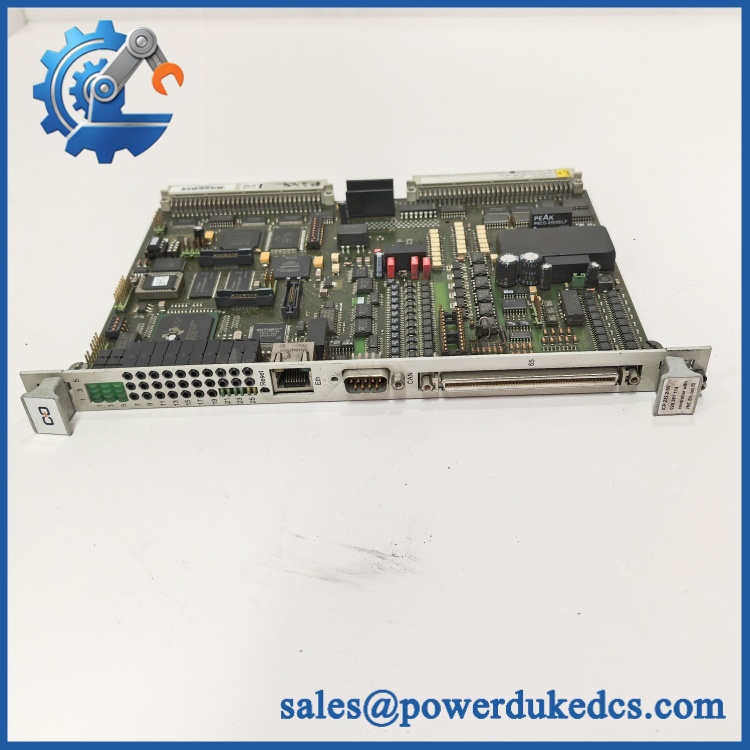
ALSTOM ICP232 029.359325
Module 5: Migration, Compatibility & Installation Traps
Replacement Matrix
Exact 029.359325 / 029.359325/07 with matching host equipment: Drop-in Replacement
When the VME chassis, board revision, firmware, connector arrangement, and application configuration match the original assembly, the controller can generally be exchanged as a direct hardware replacement.
Same family with different revision: Software Compatible / Hardware Verification Required
A different revision may require firmware, configuration, or host-system compatibility checks. Compare the PCB revision, processor configuration, memory population, and connector arrangement before installation.
Different VME controller board: Hardware Modification Required unless specifically approved
A board with a VME interface is not automatically equivalent. CAN implementation, Ethernet hardware, I/O mapping, processor architecture, memory resources, and firmware support can all differ.
⚠️ Field Traps (Watch Out)
Revision-code trap: Current service documentation identifies 029.359325/07 as an alternate spare identifier for the . Do not treat the base 029.359325 number as sufficient when the installed board carries a revision or suffix.
VME backplane trap: A board can fit mechanically while still being unsuitable for the installed VME system. Verify slot position, backplane signals, board-level addressing, I/O mapping, and host firmware before energization.
Communication-configuration trap: Ethernet and CAN interfaces may require restoration of network or node parameters after replacement. A healthy POST does not prove successful application-level communication.
Specification-source trap: Commercial listings disagree on detailed electrical specifications for this part. One record describes VME/Ethernet/CAN/I/O, while another publishes additional RS-232 and Modbus TCP information. These claims should not be treated as authoritative without the original ALSTOM equipment documentation.
Module 6: Quality Assurance SOP
Pre-Shipment QA Protocol for ALSTOM 029.359325
- Step 1 — Identity Verification: Confirm ALSTOM marking, designation, 029.359325 part number, 029.359325/07 variant where applicable, serial information, board revision, and host-equipment identification.
- Step 2 — OEM Anti-Counterfeit Visual Inspection: Inspect labels, PCB markings, component date codes, connector bodies, VME interface, CAN/Ethernet interfaces, mounting hardware, and evidence of unauthorized board repair.
- Step 3 — Mechanical Inspection: Check the PCB, VME edge connector, mounting points, front or rear connectors, keying features, and board surface for cracks, bent contacts, corrosion, contamination, or mechanical damage.
- Step 4 — Power-Supply Verification: Confirm the required board supply voltages from the installed ALSTOM VME chassis documentation before applying power. Do not infer the exact rail requirements from third-party product listings.
- Step 5 — Power-On Self-Test: Install the controller in a compatible VME test chassis and verify board initialization, processor startup, status indications, and absence of hardware diagnostics.
- Step 6 — VME Backplane Test: Confirm correct board recognition, slot communication, and expected VME bus behavior under controlled laboratory conditions.
- Step 7 — Ethernet Interface Test: Where supported by the installed board configuration, establish a controlled Ethernet connection and verify link status, packet transmission, and host-controller communication.
- Step 8 — CAN Interface Test: Connect approved CAN test equipment and verify bus initialization, node communication, message transmission, and reception without unexpected bus errors.
- Step 9 — I/O and Application Test: Run the approved host-system diagnostic or application test to confirm correct interaction between the controller, VME backplane, and connected I/O resources.
- Step 10 — Final QC Record: Record complete part number, suffix, board revision, host-platform model, supply measurements, VME results, Ethernet results, CAN results, diagnostic status, visual condition, test date, and final QC disposition.
Technical Verification Note: Current industrial service records consistently identify ALSTOM 029.359325 as an Controller Module/Board, with 029.359325/07 listed as an alternate spare identifier. One service source describes the controller as incorporating VME, Ethernet, CAN, and I/O, while another independently lists the board’s approximate shipping dimensions as 2.5 × 26.7 × 19.1 cm and weight as 0.4 kg.
Technical Data Control Note: Public sources do not provide a sufficiently authoritative ALSTOM datasheet establishing the complete electrical ratings, pinout, processor specification, operating-temperature range, or exact software compatibility for every 029.359325 revision. Those parameters should be verified from the installed equipment documentation and the physical board label before a safety- or production-critical replacement is released.











 Start Chat


