

Description
-
- Brand Alstom / AREVA T&D / GE Grid Solutions legacy
- Full Model Number MVAJ051RB0800B
- System/Series Family MVAJ05 tripping and control relay family
- Core Function Instantaneous self-reset tripping relay for protection and breaker-control circuits
- Top 3 Hardcore Specs 110 VDC relay supply | 5-contact MVAJ051 configuration | High-burden / instantaneous cut-off configuration
- Stock Status New Surplus — verify exact voltage, contact arrangement, relay links, and wiring diagram before shipment
Module 3: Technical Product Introduction
A protection trip path has little tolerance for an incorrectly configured auxiliary relay. The MVAJ051 family is a dedicated tripping and control relay series used in electrical protection schemes, and the supplied MVAJ051RB0800B identification is associated with the 110 VDC version. Current utility relay documentation identifies MVAJ051 as an instantaneous, self-reset relay with a hand-reset flag, while the AREVA T&D service manual classifies MVAJ051 as a 5-contact relay type with self-reset operation. Historical product references also show MVAJ051 variants supplied for different DC control voltages.
The electrical configuration deserves careful attention. The MVAJ05 service documentation distinguishes the relay family’s high-burden and low-burden configurations through an external link between case terminals 22 and 24; for MVAJ051, the installed link selects the high-burden condition, while removing it converts the relay to low burden. The same documentation warns that DC supply polarity must be correct and that the external connection diagram is identified on the relay’s internal rating label. Consequently, the exact RB0800B suffix, coil voltage, contact arrangement, and link status should be verified from the physical relay before replacement.
Module 4: Application Scenarios & Field Realities
- In a substation breaker trip circuit, the is used as an auxiliary tripping relay that transfers a protection command into the breaker-control wiring. Its instantaneous self-reset behavior is suited to schemes where a rapid trip command must be passed through a dedicated relay interface. National Grid’s approved-relay documentation specifically lists for tripping-service applications.
- Where a hand-reset flag is required for event indication, the provides a mechanical indication associated with the relay operation. During an outage investigation, that flag can help distinguish a completed trip operation from a relay that never received the initiating signal.
- For protection panels using high-burden tripping circuits, the factory link configuration matters. AREVA’s service documentation states that , MVAJ053, MVAJ054, and MVAJ055 are supplied as high-burden relays and can be converted to low burden by removing the link between terminals 22 and 24. A spare with the wrong link state can therefore alter the circuit characteristics even though the relay itself operates.
- During legacy protection-system maintenance, the exact relay diagram should be treated as part of the component identity. AREVA specifically instructs users to quote the full relay model and component references when ordering spares, and the connection diagram number is tied to the relay’s rating information.
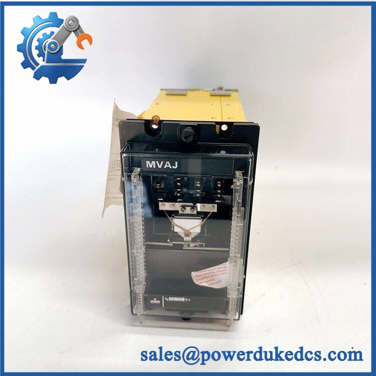
Alstom MVAJ051RB0800B
Module 5: Migration, Compatibility & Installation Traps
Replacement Matrix
Replacement Status Engineering Assessment Drop-in Replacement Yes, only for an exact MVAJ051RB0800B replacement with matching coil voltage, contact arrangement, burden configuration, terminal wiring, and approved protection scheme. Software Compatible Not applicable. This is an electromechanical protection relay without user-configured application firmware. Hardware Modification Required Normally no for an exact relay replacement. Modification may be required when changing voltage, contact configuration, burden setting, reset mode, or the associated protection scheme. ⚠️ Field Traps: Watch Out
Do not identify the relay only as “.” The MVAJ05 family contains multiple variants, including different reset methods and contact arrangements. AREVA documentation lists as the 5-contact self-reset version, while MVAJ053, MVAJ054, and MVAJ055 have different reset functions.
Verify the coil/control voltage. Current utility documentation identifies the standard references as 30 VDC and 110 VDC variants, while historical product listings also show other voltage configurations in the broader family. The supplied RB0800B identification has been associated with the 110 VDC version, but the physical rating label should govern the final procurement specification.
Check terminals 22 and 24. The MVAJ service manual explicitly uses the link between these terminals to select high- or low-burden operation. Removing or retaining that link changes the relay’s electrical burden and can affect the protection circuit.
Polarity is not optional on a DC relay. AREVA’s commissioning procedure specifically warns that DC supplies must be wired with the correct polarity. Verify the schematic before applying the control voltage.
Do not substitute on contact count alone. The family is part of a broader tripping-relay series with different contact and reset configurations. The replacement must reproduce the complete protection function, not merely the number of visible terminals.
Module 6: Quality Assurance SOP
A surplus MVAJ051RB0800B should receive relay-level electrical and mechanical testing before shipment. Coil operation alone is not enough; contact timing, contact integrity, burden configuration, and reset behavior also matter.
- OEM anti-counterfeit visual inspection: Verify Alstom/AREVA/GE Grid Solutions identification, exact MVAJ051RB0800B marking, relay case, rating label, terminal arrangement, flag mechanism, and manufacturer markings against controlled references.
- Part-number and traceability check: Record the complete relay number, serial number, voltage marking, connection-diagram number, and manufacturing/date code.
- Mechanical inspection: Check the relay case, mounting hardware, terminal blocks, contact mechanism, reset mechanism, flag assembly, and accessible insulation for cracks, corrosion, contamination, or unauthorized modification.
- Rating-label verification: Confirm the control voltage and connection-diagram reference directly from the relay’s internal rating label before energization. AREVA documentation specifically directs technicians to use this information during commissioning.
- Coil resistance test: Measure the relay coil resistance under de-energized conditions and compare it with the controlled reference for the exact voltage variant.
- Insulation test: Perform the approved coil-to-contact and contact-to-contact insulation test using the applicable protection-relay maintenance procedure.
- Pickup/dropout test: Apply a controlled DC source and verify reliable relay pickup and dropout at the approved thresholds.
- Instantaneous operation test: Confirm the relay operates without the intentional delayed-reset characteristics associated with other MVAJ family variants.
- Contact continuity test: Verify every normally open and normally closed contact in the installed five-contact configuration using a calibrated low-current continuity test.
- Contact-resistance test: Measure closed-contact resistance and check for unstable readings, oxidation, or excessive resistance.
- High/low burden verification: Inspect and document the 22–24 link condition. Confirm the relay is configured for the burden state specified by the protection scheme.
- Self-reset verification: Energize the relay, operate the trip function, and confirm the mechanism returns correctly when the initiating signal is removed, subject to the specific wiring scheme.
- Hand-reset flag verification: Confirm the mechanical flag operates correctly and provides the expected visual indication after relay operation where fitted.
- Contact timing test: Use a relay test set or oscilloscope-equipped timing fixture to verify operate and release times against the approved engineering specification.
- DC polarity verification: Confirm the test fixture and relay terminals are correctly polarized before energization.
- Trip-circuit simulation: Connect the relay to a representative breaker-trip circuit or approved simulator and verify correct transfer of the trip command through all relevant contacts.
- Communication handshake verification: Not applicable as a standalone device. Acceptance should instead verify correct electrical interaction with the associated protection relay and breaker-control circuit.
- Fault-condition test: Where the approved procedure permits, simulate coil interruption, contact failure, or control-voltage loss and verify the expected protection-scheme response.
- Extended endurance test: Cycle the relay under controlled conditions while monitoring coil current, contact resistance, mechanical flag behavior, pickup/dropout consistency, and temperature.
- Final QC record: Document exact model, coil voltage, contact arrangement, burden-link state, coil resistance, insulation results, pickup/dropout values, contact resistance, timing results, reset/flag behavior, trip-circuit simulation, traceability, and packaging condition.
Technical Identification Note: The supplied ALSTOM MVAJ051RB0800B designation belongs to the MVAJ05 tripping and control relay family. Current utility documentation identifies as an instantaneous self-reset relay with a hand-reset flag, while the AREVA service manual identifies it as a 5-contact relay and documents the selectable high-/low-burden link between terminals 22 and 24. Independent historical trade records associate with a 110 VDC relay configuration. Because the complete suffix governs voltage and contact configuration, the physical rating label and relay connection diagram should be verified before procurement.











 Start Chat


