

Description
- Brand: ALSTOM
- Full Model Number: STO1726KO1
- System/Series Family: ALSTOM railway and industrial control/protection equipment
- Core Function: Board-level control and protection interface used within an ALSTOM drive or interlock assembly
- Top 3 Hardcore Specs: 24 VDC-class control circuitry; board-level industrial interface; exact I/O and electrical configuration revision-dependent
- Stock Status: Verify current New Surplus, Factory Sealed, or Fully Tested Refurbished condition before order
Module 3: Technical Product Introduction
A board carrying a safety or drive-interlock function cannot be evaluated safely from its part number alone. ALSTOM STO1726KO1 appears in current industrial service records as an ALSTOM control/protection board associated with drive and interlock equipment. Several commercial sources instead describe it as a Safety Torque Off module, while another ALSTOM inventory page labels it as a digital-input module. The conflicting classifications indicate that the exact host assembly and revision should be verified from the physical nameplate and equipment documentation before treating any one description as definitive.
Public technical evidence is not sufficient to establish a reliable complete datasheet for the exact STO1726KO1 revision. One current commercial listing states 24 VDC ±10% control power, while other listings publish specific response times, output ratings, isolation values, and safety certifications that are not independently supported by ALSTOM primary documentation located for this exact part.For procurement and field replacement, the correct engineering approach is to preserve the exact board revision, connector population, host cabinet, and original circuit drawing rather than inferring specifications from unrelated STO products.
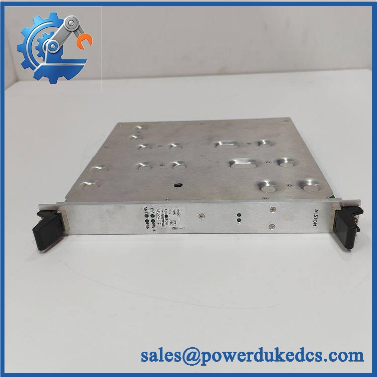
ALSTOM STO1726KO1
Module 4: Application Scenarios & Field Realities
- Inside an ALSTOM drive or protection cabinet, STO1726KO1 is treated as a board-level control/protection component rather than a generic PLC I/O card. The mating assembly, board position, connector keying, and host controller determine its actual system role.
- During brownfield maintenance, the complete identification string on the PCB matters. Record STO1726KO1 together with hardware revision, barcode, serial number, connector markings, and the host equipment designation before removing the original board.
- Where emergency-stop or drive-interlock functions are involved, a successful power-up is not enough. The engineer should verify the complete safety chain, including input activation, interlock logic, output inhibition, diagnostic feedback, and the downstream drive response. The precise function must follow the installed ALSTOM schematic rather than a generic STO description.
- For railway equipment or harsh industrial environments, application-specific environmental and vibration requirements may apply. Current listings associate STO1726KO1 with railway and industrial control equipment, but exact environmental ratings for the part should be taken from the host equipment documentation rather than assumed from the product code.
Module 5: Migration, Compatibility & Installation Traps
Replacement Matrix
Exact with matching host assembly and revision: Drop-in Replacement
When the PCB revision, connector configuration, host rack, firmware, and electrical interface match the removed board, replacement can generally be performed as a like-for-like board exchange.
Same with different hardware revision: Software Compatible / Hardware Verification Required
Compare PCB revision, component population, firmware requirements, connector assignments, and host-system configuration before installation. A base part-number match alone does not establish complete equivalence.
Generic STO or drive-safety module substituted for : Hardware Modification Required
An independent STO device may perform a similar safety function while using completely different input logic, output circuitry, isolation, diagnostic behavior, or drive interface. It should not be considered a direct replacement without an engineered redesign.
⚠️ Field Traps (Watch Out)
Identity-conflict trap: Current public sources do not agree on the exact classification of . One source calls it a Safety Torque Shutdown module, another labels it an industrial control board for drive/protection interlocks, and another page lists it as a digital-input module.This makes physical identification and host-equipment documentation mandatory.
Unverified-rating trap: Some commercial listings publish detailed figures such as 10 A/600 V output, 2 ms response time, 2.5 kVAC isolation, or SIL 3 certification. These claims are not sufficiently corroborated by an ALSTOM primary-source document for this exact part number. Do not use them as approved design parameters without independent verification.
Host-interface trap: Board-level replacement must preserve the connector arrangement and slot position. A visually similar ALSTOM board can have different backplane or field-interface assignments.
Safety-validation trap: Where participates in a drive-protection or emergency-stop function, post-replacement verification should test the complete safety chain, not just board diagnostics.
Module 6: Quality Assurance SOP
Pre-Shipment QA Protocol for ALSTOM
- Step 1 — Identity Verification: Confirm ALSTOM marking, designation, complete PCB part number, hardware revision, serial number, barcode, and host-equipment reference.
- Step 2 — OEM Anti-Counterfeit Visual Inspection: Inspect labels, PCB markings, component references, manufacturing codes, connector bodies, board finish, fasteners, and evidence of unauthorized rework.
- Step 3 — Mechanical Inspection: Check the PCB, edge connectors, mating plugs, mounting holes, retaining hardware, connector keys, and board surface for cracks, corrosion, contamination, or impact damage.
- Step 4 — Electrical Interface Verification: Before energization, establish the exact supply and signal requirements from the ALSTOM equipment drawing. Do not rely on a generic 24 VDC rating from a reseller listing.
- Step 5 — Power-On Self-Test: Install the board in the approved host assembly or engineering test fixture and verify startup behavior, status indication, diagnostics, and host-board recognition.
- Step 6 — Input/Control Signal Test: Exercise each documented control or interlock input using an isolated laboratory source and compare the response with the approved equipment schematic.
- Step 7 — Output/Interlock Test: Where the test fixture supports it, verify each documented output or inhibit function under controlled conditions. Record commanded state and actual response.
- Step 8 — Communication and Diagnostic Verification: Confirm all applicable backplane, serial, CAN, Ethernet, or local diagnostic interfaces only where those interfaces are explicitly documented for the exact board revision.
- Step 9 — Safety-Function Verification: If the board participates in a drive shutdown or interlock chain, perform the approved end-to-end safety functional test with the downstream drive isolated and under controlled commissioning procedures.
- Step 10 — Final QC Record: Record complete part number, hardware revision, host assembly, measured supply, all tested inputs and outputs, diagnostic results, safety-function result where applicable, visual condition, test date, and final QC disposition.
Technical Verification Note: Current public records identify as a board-level component associated with ALSTOM industrial/railway control and protection equipment, but the exact functional classification is inconsistent across commercial sources. One source describes it as a Safety Torque Shutdown module, another as an industrial control board for drive/protection interlocks, and another as a digital-input module.
Technical Data Control Note: Because no sufficiently authoritative ALSTOM primary-source datasheet for the exact revision was located, detailed ratings such as exact output current, response time, isolation voltage, safety level, dimensions, temperature range, and supported protocols should not be treated as confirmed specifications. For a production or safety-critical replacement, use the physical board label, host equipment drawing, approved bill of materials, and original ALSTOM documentation as the controlling references.











 Start Chat


