

Description
- Brand: ALSTOM
- Full Model Number: V-ASSY-A376
- System/Series Family: ALSTOM industrial control equipment — exact host family requires nameplate verification
- One-Sentence Core Function: Configuration-specific ALSTOM assembly identified by the V-ASSY-A376 reference
- Top 3 Hardcore Specs: V-ASSY-A376 assembly reference; configuration-specific hardware; exact electrical function requires OEM/host-system verification
- Stock Status: New Surplus / Fully Tested Refurbished — verify physical nameplate, revision, and host equipment before shipment
Module 3: Technical Product Introduction
A part number beginning with V-ASSY should be treated as an assembly identifier until the actual OEM documentation establishes its function. The supplied ALSTOM V-ASSY-A376 can be preserved as an exact inventory reference, but available public technical sources do not provide sufficiently reliable evidence to classify it as a CPU, I/O module, drive controller, power module, or communications card.
That distinction matters during procurement. No authoritative source located for this exact designation establishes channel count, rated voltage, current capacity, protocol, processor type, dimensions, weight, or compatible replacement models. Publishing invented numerical specifications would create a significant installation risk. For this part, the physical nameplate, PCB assembly marking, host-equipment model, and ALSTOM project documentation should control the technical description.
Module 4: Application Scenarios & Field Realities
- During a brownfield ALSTOM cabinet replacement, identify the host machine first. The V-ASSY-A376 reference alone does not establish whether the assembly belongs to a drive, traction system, excitation cabinet, automation rack, or another ALSTOM platform.
- When an installed assembly has failed, photograph both sides of the unit before removal. Record every secondary identification code, PCB number, revision, connector label, and serial number. Those details are often more useful than the abbreviated commercial model.
- For surplus inventory, retain V-ASSY-A376 exactly as printed. Avoid rewriting it as a generic “control board” unless the original equipment documentation confirms that classification.
- During migration work, compare the replacement with the removed assembly mechanically before applying power. Connector geometry alone is not enough; internal wiring, revision level, and assembly-specific configuration can change the electrical function.
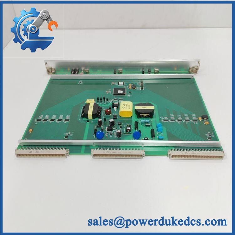
ALSTOM V-ASSY-A376
Module 5: Migration, Compatibility & Installation Traps
Replacement Matrix
| Replacement Type | Assessment |
|---|---|
| Drop-in Replacement | Unknown / Conditional — requires exact host-system and assembly identification |
| Software Compatible | Unknown — no reliable public firmware or configuration compatibility matrix established for this exact reference |
| Hardware Modification Required | Unknown — depends on the confirmed assembly function and mating equipment |
⚠️ Field Traps — Watch Out
1. Do not infer the function from “V-ASSY.”
The designation indicates an assembly-style reference but does not, by itself, prove that the item is a controller, I/O card, power supply, or communication board.
2. Secondary part numbers are critical.
Check for additional ALSTOM assembly numbers, PCB identifiers, component references, revision codes, and barcode labels. Two assemblies with the same commercial reference may still require revision-level confirmation.
3. Verify the host equipment before energization.
Do not apply a presumed 24 VDC, 110 VAC, 220 VAC, or other supply based on a visually similar ALSTOM assembly. The applicable electrical data must come from the confirmed host-system documentation.
4. Connector fit does not establish interchangeability.
A mechanically compatible assembly may have a different internal configuration. Verify pin assignments and wiring against the approved drawing before installation.
Module 6: Quality Assurance SOP
- OEM anti-counterfeit visual inspection — inspect ALSTOM markings, V- identification, labels, serial information, PCB markings, connectors, enclosure, and manufacturing codes.
- Exact part-number verification — confirm character-for-character against the purchase order and physical item.
- Secondary identification capture — photograph every visible assembly number, PCB number, revision code, barcode, connector designation, and component label.
- Host-system verification — identify the exact ALSTOM drive, automation cabinet, traction controller, excitation system, or other equipment in which the original assembly is installed.
- Mechanical inspection — inspect connectors, mounting hardware, PCB surfaces, terminal interfaces, cooling components, and insulation for corrosion, contamination, cracks, impact, or bent contacts.
- Configuration verification — compare the assembly with the removed unit and approved cabinet drawings before connecting any power source.
- Power-on self-test (POST) — perform a controlled startup only after the correct supply requirements have been independently verified from the applicable OEM documentation. Record status indications, current draw, and abnormal temperature rise.
- Functional test — test only the confirmed function of the assembly using an approved ALSTOM-compatible laboratory fixture.
- I/O verification where applicable — where the assembly is confirmed to contain signal interfaces, perform point-to-point or channel-by-channel testing against the verified pinout.
- Parameter/firmware verification where applicable — record firmware, hardware revision, calibration information, and stored configuration before release.
- Communication handshake verification where applicable — test only the communication interface confirmed by the host-system documentation. Do not assign Ethernet, serial, CAN, or fieldbus capability without evidence.
- System-level validation — where a suitable test environment exists, verify correct interaction with the associated ALSTOM equipment before field release.
- Final QC and packaging — document the exact identifier, revision information, test results, inspection photographs, ESD protection, and packaging condition before shipment.
Engineering note: The exact reference could not be reliably matched to an authoritative public technical specification during verification. Therefore, the PDP intentionally avoids unsupported claims about voltage, I/O count, protocol, processor architecture, dimensions, or application family. For this assembly, the customer’s physical nameplate and ALSTOM equipment documentation should be treated as the controlling technical source.











 Start Chat


