

Description
- Brand: ALSTOM
- Full Model Number: VIIB16-C / 12011-105-00 / V1.0.0
- System/Series Family: ALSTOM VIIB-series rail control and distributed I/O architecture
- Core Function: 16-channel isolated digital input interface for rack-mounted railway control equipment
- Top 3 Hardcore Specs: 16 isolated digital inputs; 24 VDC nominal field level; proprietary rack backplane interface
- Module Category: Digital Input / I/O Interface Module
- Hardware Version: 12011-105-00
- Version Marking: V1.0.0
- Installation: Plug-in rack module
- Field Interface: Front-side field termination
- Stock Status: New Surplus or Fully Tested Refurbished; exact revision to be confirmed
Publicly indexed references consistently identify VIIB16-C / 12011-105-00 as an ALSTOM VIIB-series interface module, while railway certification records separately identify VIIB16-C as the hardware version associated with the 12011-105 family. Product references describe the module as a 16-channel isolated digital-input interface.
Module 3: Technical Product Introduction
A digital-input interface in railway control equipment has to preserve clean state detection while the cabinet is exposed to vibration, switching transients, and electrical noise. The ALSTOM VIIB16-C 12011-105-00 V1.0.0 is identified as a VIIB-series digital interface module, with available technical listings specifying 16 isolated digital input channels intended for rack-based industrial and railway control applications. The module is designed to exchange I/O information with the host controller through the system’s proprietary backplane rather than acting as a standalone programmable CPU.
Configuration control is important with this part number. The designation combines the VIIB16-C hardware family, 12011-105-00 assembly identifier, and V1.0.0 version marking. Available reseller documentation describes a 24 VDC-class digital-input architecture, but authoritative public documentation does not provide enough evidence to publish a complete electrical timing table, input-current limit, exact isolation rating, or connector pinout for this exact revision. Those values should therefore be taken from the equipment drawing or original ALSTOM documentation before a field replacement is approved.
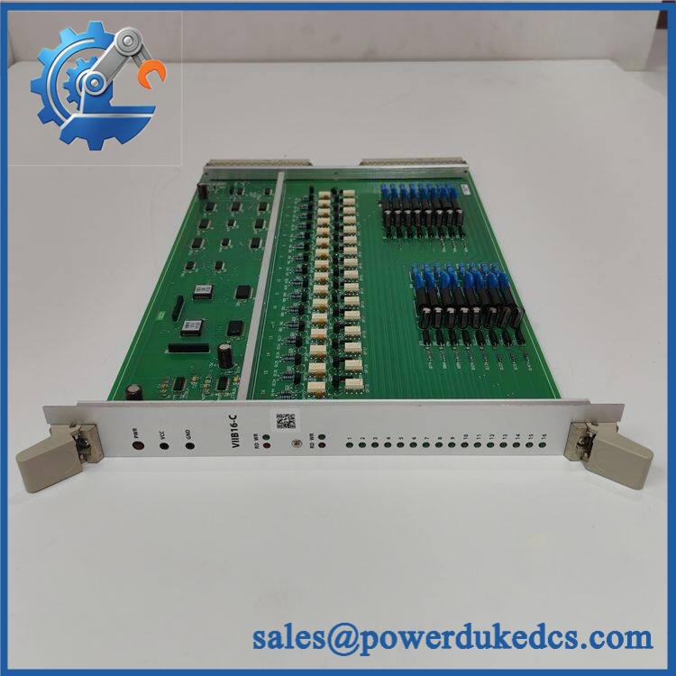
ALSTOM VIIB16-C 12011-105-00 V1.0.0
Module 4: Application Scenarios & Field Realities
- In railway auxiliary-control cabinets, the VIIB16-C can be used to acquire discrete equipment states such as contactor feedback, switch positions, interlocks, and other binary status signals. The isolated-input architecture is particularly relevant where field circuits may sit at different electrical potentials.
- For traction or vehicle electrical control equipment, a rack-mounted digital-input module provides the controller with discrete status information without requiring every field device to terminate directly on the CPU assembly. During maintenance, technicians should therefore verify the complete I/O chain: field contact, wiring, terminal interface, , and host backplane.
- Where cabinet vibration is significant, connector seating and mechanical retention deserve the same attention as the input electronics. A marginal rack connection can produce intermittent channel changes that look like unstable field contacts (particularly on older equipment with repeated module removal).
- During fleet or cabinet refurbishment, the full identifier should be retained in the asset record. Railway documentation distinguishes 12011-105-XX from the earlier family designation, so the suffix and hardware version should not be discarded when replacing obsolete modules.
Module 5: Migration, Compatibility & Installation Traps
Replacement Matrix
Replacement classification: Drop-in Replacement when the existing installation specificals 12011-105-00 V1.0.0 with the same rack, field termination arrangement, hardware revision, and application configuration.
Software compatibility: Configuration verification required. The module is an I/O interface rather than the main application processor, but channel mapping, input logic, diagnostics, and rack configuration remain dependent on the host control system.
Cross-model replacement: Hardware and configuration verification required., , and other VIIB-series modules may share similar naming and mechanical concepts while carrying different hardware revisions or functions. A compatible-looking connector does not establish electrical equivalence.
Field Traps — Watch Out
1. Match the complete hardware identifier. The customer’s reference contains three useful identification layers: , 12011-105-00, and V1.0.0. Do not procure solely from “” because the C-series hardware is separately identified in railway documentation.
2. Verify the field voltage at the module terminals. Available product references describe the unit as a 24 VDC-class digital-input interface, but the exact input thresholds and tolerance for this revision should be confirmed from the original ALSTOM documentation before energization.
3. Inspect the backplane interface before replacing the module. A damaged or oxidized rack connector can create multiple apparent input-channel faults. Compare the suspect module in another approved rack position only when the ALSTOM maintenance procedure permits such a test.
4. Preserve the original field wiring map. With isolated digital inputs, channel-to-channel wiring errors can be difficult to identify from the system display alone. Record every terminal and channel association before removal.
5. Do not infer railway certification from the part number alone. The presena identification in railway documentation confirms the hardware family, but application-specific approval depends on the complete equipment configuration and applicable certification conditions.
Module 6: Quality Assurance SOP
Pre-Shipment Inspection Protocol forM 12011-105-00 V1.0.0
- OEM identity inspection: Verify ALSTOM m, designation, 12011-105-00 assembly number, V1.0.0 marking, serial information, and all visible revision labels.
- Configuration verification: Confirm that the hardware correspondse revision rather than a visually similar or other I/O module.
- Mechanical inspection: Examine the enclosure, PCB, rack guides, retaining hardware, connectors, labels, and terminal interface for cracks, deformation, corrosion, contamination, or unauthorized modification.
- Backplane connector inspection: Check mating contacts for oxidation, bent pins, contamination, damaged plating, or mechanical wear.
- Field-terminal inspection: Examine terminal interfaces for loose hardware, damaged insulation, corrosion, discoloration, or signs of overheating.
- Power-on verification: Install the module in a verified compatible ALSTOM test rack and apply only the documented supply arrangement for the specific system.
- POST observation: Record startup behavior, module status indications, current draw, and any immediate hardware or communication diagnostics.
- 16-channel verification: Exercise all 16 digital-input channels independently using a controlled signal source.
- Threshold verification: Apply representative input voltages around the documented operating region for the installed revision and record the measured ON/OFF transition points.
- Isolation verification: Perform an approved isolation test between representative input channels and the appropriate reference circuits using the limits specified by the original ALSTOM documentation.
- Input timing test: Apply controlled state transitions and record response time for representative channels; compare the result with the original system specification rather than an assumed generic digital-input value.
- Backplane communication test: Connect the module to an appropriate host controller or test fixture and verify correct data exchange through the rack interface.
- Channel mapping verification: Confirm that every physical input terminal corresponds to the expected logical channel in the host-system configuration.
- Fault simulation: Where the test fixture permits, simulate open, short, and loss-of-signal conditions appropriate to the module’s documented diagnostic behavior.
- Extended operation test: Run representative input activity for an extended period while monitoring for intermittent state changes, communication errors, resets, or abnormal thermal behavior.
- Thermal observation: Check the module surface and critical components for abnormal heating under representative rack loading.
- Final QC record: Record exact model, assembly number, version, serial number, test rack, supply conditions, all 16 channel results, diagnostic observations, communication results, test duration, and inspector approval.
- ESD-controlled packaging: Place the module in an ESD-safe package and protect connectors, terminals, PCB surfaces, and mechanical retention features against electrostatic discharge, moisture, contamination, vibration, and impact.
Procurement note: M 12011-105-00 V1.0.0 is best treated as a revision-controlled VIIB-series digital I/O interface module. The strongest available references support the 16-channel isolated digital-input description and the 12011-105 hardware family, while railway certification records explicitt under 12011-105-XX. Exact electrical thresholds, power consumption, connector pinout, and environmental limits should be verified from the installed equipment documentation before engineering substitution.











 Start Chat


