

Description
- Brand: ALSTOM
- Full Model Number: VOOB8-B / 12004-106-04 / VER V1.0.0
- System/Series Family: ALSTOM SBS serial-bus remote I/O architecture
- Core Function: 8-channel digital output interface for solenoid valves, hydraulic actuators, relays, and auxiliary switching circuits
- Top 3 Hardcore Specs: 8 digital outputs; optically isolated field interface; 24 VDC field-output class
- Stock Status: Verify current New Surplus, Factory Sealed, or Fully Tested Refurbished condition before order
Module 3: Technical Product Introduction
A valve-control output failure can leave a turbine governing cabinet unable to energize an actuator even when the upstream controller and serial bus remain operational. ALSTOM VOOB8-B 12004-106-04 VER V1.0.0 is identified in current industrial service records as an 8-channel digital valve output board for ALSTOM’s SBS serial-bus remote I/O architecture. The module is intended to convert controller commands into discrete field outputs for solenoid valves, hydraulic actuator coils, relays, and related switching devices. Current technical listings describe the board as a Eurocard plug-in assembly used in ALSTOM turbine governing systems.
The engineering focus is the field-output interface, not general-purpose PLC processing. Available technical records identify eight isolated digital output channels, front-panel channel indication, and a 24 VDC-class field interface, with the board communicating through the host rack’s SBS backplane rather than acting as an independent Ethernet controller. Public sources do not provide a sufficiently authoritative ALSTOM primary datasheet establishing exact per-channel current, isolation voltage, response time, or temperature ratings for this precise V1.0.0 assembly. Those values should therefore be confirmed from the installed cabinet documentation before they are used for engineering acceptance.
Module 4: Application Scenarios & Field Realities
- On steam-turbine governing systems, VOOB8-B can provide the discrete commands required by auxiliary solenoid valves and actuator control circuits. The board sits within the remote I/O architecture, so a channel fault should be diagnosed together with the SBS communication path and field termination rather than as an isolated output-card problem.
- When hydraulic actuator coils are controlled from the turbine cabinet, the output channel’s actual load current matters. A coil that appears compatible by voltage may still exceed the board’s permitted current or produce inductive transients that need to be handled by the specified field interface.
- During brownfield replacement of an SBS remote-I/O board, the complete identifier should be preserved: VOOB8-B, 12004-106-04, and V1.0.0. Current product records consistently associate this combination with an 8-channel digital-output board, although some commercial descriptions use broader terms such as control board or electronic output module.
- Where the field circuit includes interlocks or relay logic, verify each output’s original point assignment before reconnection. Eight outputs do not mean every channel has the same downstream function; cabinet drawings may assign individual points to valve coils, permissive relays, alarms, or auxiliary controls.
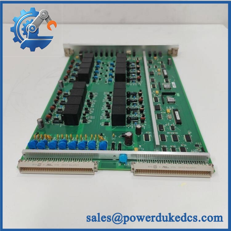
ALSTOM VOOB8-B 12004-106-04 V1.0.0
Module 5: Migration, Compatibility & Installation Traps
Replacement Matrix
Exact VOOB8-B 12004-106-04 V1.0.0 with matching SBS host configuration: Drop-in Replacement
When the host rack, board revision, connector arrangement, field termination, and application configuration match the original assembly, replacement can generally be handled as a like-for-like board exchange.
VOOB8-B with a different hardware or firmware revision: Software Compatible / Hardware Verification Required
The V1.0.0 marking should be retained in the spare-parts record. Verify host-controller compatibility, board revision, output assignment, and any revision-specific service instructions before commissioning.
Different ALSTOM digital-output board: Hardware Modification Required unless explicitly approved
A board with eight digital outputs is not automatically equivalent. SBS bus addressing, connectorization, field voltage, output-current capability, and protection circuitry can differ between board families.
⚠️ Field Traps (Watch Out)
Output-current uncertainty: Public listings identify the board as a 24 VDC-class digital output module, but they do not provide a sufficiently reliable primary-source current rating for each channel. Do not use the generic 24 VDC description as proof that any arbitrary solenoid or hydraulic coil is acceptable.
Revision trap: The exact designation includes VER V1.0.0. A visually similar board carrying another revision should not be released automatically; compare revision records, PCB population, host compatibility, and approved ALSTOM documentation.
Backplane-communication trap: is described as an SBS remote-I/O board. A successful local power-up does not prove that the host controller is addressing the board correctly. Verify the SBS communication path, rack position, board recognition, and channel mapping after installation.
Inductive-load trap: Valve and relay coils generate transient voltage when de-energized. Confirm that the installed field interface uses the specified suppression arrangement and do not bypass protection components during troubleshooting.
Module 6: Quality Assurance SOP
Pre-Shipment QA Protocol for ALSTOM 12004-106-04 V1.0.0
- Step 1 — Identity Verification: Confirm ALSTOM marking, designation, 12004-106-04 part number, V1.0.0 revision, serial information, and associated SBS rack reference.
- Step 2 — OEM Anti-Counterfeit Visual Inspection: Inspect the ALSTOM label, PCB markings, component references, connector bodies, board finish, indicator legends, and evidence of unauthorized rework.
- Step 3 — Mechanical Inspection: Check the Eurocard PCB, edge connector, front-panel interface, mounting hardware, connector retention, and board surface for cracks, contamination, corrosion, or bent contacts.
- Step 4 — Electrical Interface Verification: Establish the exact board supply and field-output requirements from the approved ALSTOM cabinet documentation before energization. Do not infer undocumented current limits from reseller specifications.
- Step 5 — Power-On Self-Test: Install the board in a compatible SBS remote-I/O test rack and verify expected startup behavior, board recognition, and status indications.
- Step 6 — Eight-Channel Output Test: Exercise all eight channels individually using controlled representative loads. Record output state, measured voltage, load current, and channel indication.
- Step 7 — Isolation Verification: Where the laboratory procedure supports it, verify the field-to-logic isolation using an approved insulation/isolation test suitable for the board’s documented construction.
- Step 8 — Protection Test: Test representative output channels with controlled fault simulations to verify the documented over-current or short-circuit response without exposing production wiring to uncontrolled faults.
- Step 9 — SBS Communication Handshake Verification: Confirm successful board recognition and command transfer through the SBS host interface, including correct channel-state reporting.
- Step 10 — Final QC Record: Record complete part number, revision, serial number, host test rack, all eight output results, measured supply and load values, diagnostic status, communication test result, visual condition, test date, and final QC disposition.
Technical Verification Note: Current industrial sources identify ALSTOM 12004-106-04 VER V1.0.0 as an 8-channel digital valve output board used in ALSTOM SBS serial-bus remote-I/O systems. The available descriptions specify optically isolated digital outputs, a 24 VDC-class field interface, front-panel channel indication, and Eurocard plug-in construction.
Technical Data Control Note: The public evidence is inconsistent on detailed numerical ratings. One commercial source incorrectly classifies the part as a traction circuit breaker and publishes 1500 VDC / 3000 A values that are clearly incompatible with the board-level description. Those values should be disregarded for this product. Exact output current, isolation rating, operating-temperature range, dimensions, and certification data should be taken from the installed ALSTOM equipment documentation or the physical board specification.











 Start Chat


