

Description
- Brand ALSTOM
- Full Model Number VPS 12004-102-03 V1.0.0
- System/Series Family ALSTOM iLOCK / interlocking control electronics
- Core Function VPS power-supply module serving the control-rack power architecture
- Top 3 Hardcore Specs 12004-102-03 hardware designation | V1.0.0 version marking | Rack-mounted VPS power module
- Stock Status New Surplus — verify exact hardware revision, rack compatibility, connector configuration, and approved supply requirements before shipment
Module 3: Technical Product Introduction
A defective rack power module can take an otherwise healthy control assembly offline, making downstream I/O or processor cards appear faulty. ALSTOM VPS 12004-102-03 V1.0.0 is identified in current railway certification material as a VPS module within the iLOCK interlocking computer subsystem. The same certification records list VPS hardware variants 12004-102-01, 12004-102-02, and 12004-102-03, alongside VLE, DVCOM, IOBUS2, IOBE2, VIIB16, and VOOB8 modules. This places VPS within a defined rail-control hardware architecture rather than as a generic industrial power supply.
Secondary technical references describe the 12004-102-03 assembly as a Eurocard-style regulated power supply board for ALSTOM SBS serial-bus control racks, with a reported 24 VDC rack input and regulated low-voltage outputs. Those electrical figures are not sufficiently supported by a primary ALSTOM datasheet in the available public material, however, and other supplier pages incorrectly classify the same part as an I/O or control-processing board. For procurement, VPS 12004-102-03 V1.0.0 should therefore be treated as a rack power-supply module pending verification of the physical board and controlled system documentation.
Module 4: Application Scenarios & Field Realities
- Within an ALSTOM railway interlocking cabinet, VPS forms part of the power architecture supporting the control electronics. The certification configuration places VPS 12004-102-03 in the same interlocking computer subsystem as VLE, IOBUS2, IOBE2, VIIB16, and VOOB8.
- When several control boards appear to lose communication simultaneously, inspect the shared rack power path before replacing individual processor or I/O boards. A common supply disturbance can create multiple downstream symptoms at once.
- During replacement of a legacy Eurocard assembly, connector position and rack backplane assignment deserve close attention. One current technical listing describes VPS 12004-102-03 as a dedicated regulated supply board for ALSTOM SBS serial-bus control racks, so the mating rack architecture must be confirmed rather than assumed.
- For iLOCK equipment maintenance, preserve the exact version marking V1.0.0 in the service record. The CRCC certification material confirms the broader VPS 12004-102-XX hardware family but does not establish unrestricted interchangeability between all listed revisions.
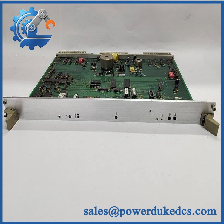
Alstom VPS 12004-102-03 V1.0.0
Module 5: Migration, Compatibility & Installation Traps
Replacement Matrix
| Replacement Status | Engineering Assessment |
|---|---|
| Drop-in Replacement | Yes, when replacing an identical VPS 12004-102-03 V1.0.0 assembly in the same approved ALSTOM rack and power architecture. |
| Software Compatible | Normally not applicable to the power-conversion function itself; however, the host control system must accept the installed hardware revision and associated monitoring arrangement. |
| Hardware Modification Required | Normally no for an exact replacement. Modification may be required when changing rack generations, connector arrangements, supply architecture, or VPS hardware revisions. |
⚠️ Field Traps: Watch Out
Do not classify V1.0.0 as firmware without evidence. The available railway certification material treats the 12004-102-03 designation as a hardware configuration entry, while supplier pages use V1.0.0 inconsistently. Preserve the complete printed marking rather than assigning an undocumented firmware meaning.
Verify the actual function from the physical board. Public listings disagree significantly: one describes VPS 12004-102-03 as a rack power-supply board, another calls it an embedded I/O module, and another labels it a control board. The rack position, PCB silkscreen, connector arrangement, and system BOM should govern the final description.
Do not apply an assumed 24 VDC test source. A secondary source reports 24 VDC rack input, while other pages provide unsupported AC-input specifications. Until the actual electrical drawing is confirmed, laboratory energization should use the documented supply requirement for the specific hardware revision.
Check the complete VPS family before substitution. CRCC certification material lists 12004-102-01, 12004-102-02, and 12004-102-03 as VPS hardware variants. Their presence in the same product family does not by itself prove electrical or mechanical interchangeability.
Module 6: Quality Assurance SOP
Because publicly available specifications conflict, the first QA gate for VPS 12004-102-03 should be exact identification, followed by controlled rack-level power testing.
- OEM anti-counterfeit visual inspection: Verify ALSTOM identification, VPS 12004-102-03 marking, V1.0.0 version marking, PCB identification, connector geometry, Eurocard construction, and visible manufacturing labels.
- Part-number and traceability check: Record the complete 12004-102-03 designation, revision/version marking, serial number, manufacturing date code, and host-rack reference.
- Mechanical inspection: Examine the backplane connector, card guides, ejector hardware, PCB surface, power connectors, and accessible components for bent contacts, corrosion, contamination, cracking, discoloration, or unauthorized rework.
- Rack-position verification: Compare the module’s intended slot and mating backplane connector against the approved ALSTOM cabinet drawing before energization.
- Power-path inspection: Check accessible fuse elements, terminals, connectors, and board traces for overheating, carbonization, loose connections, or abnormal discoloration.
- Controlled power-input verification: Determine the approved input voltage from the exact rack documentation before applying laboratory power. Do not rely on conflicting secondary listings.
- Power-on self-test (POST): Energize the board in a compatible ALSTOM test rack and record all expected power, status, alarm, and diagnostic indications.
- Output-voltage verification: Where the controlled schematic identifies regulated output rails, measure each rail under no-load and representative-load conditions and compare the readings with the approved specification.
- Load test: Apply controlled electronic loads to each documented output rail while monitoring voltage regulation, current behavior, ripple, and thermal response.
- Over-current protection test: Where the approved test fixture permits, introduce a current-limited overload and verify the specified protective response without applying an uncontrolled short circuit.
- Over-voltage protection test: Verify the documented protection function using a controlled laboratory method where the hardware specification supports such testing.
- Thermal inspection: Monitor component and connector temperatures during an extended representative load test, paying particular attention to regulators, power semiconductors, transformers where fitted, and high-current terminals.
- Backplane verification: Confirm that the VPS module supplies the expected downstream rack rails without abnormal voltage drop or excessive current demand.
- System recognition test: Verify that the associated iLOCK control subsystem initializes correctly with the tested VPS installed and that downstream modules remain available.
- Communication handshake verification: The VPS itself should not be treated as a standalone Ethernet or Modbus interface unless the exact hardware documentation confirms such functionality. Validate the complete rack communication chain after the supply rails have been proven.
- Fault-response test: Apply controlled supply interruption or diagnostic conditions permitted by the maintenance procedure and verify the expected rack-level alarm or recovery behavior.
- Extended-run test: Operate the complete representative rack under normal power load while monitoring voltage stability, ripple, temperature, resets, downstream module alarms, and intermittent failures.
- Final QC record: Document exact hardware/version marking, rack position, input supply used, output-rail measurements, load-test values, protection responses, thermal observations, system recognition, communication status, extended-run results, traceability, and packaging condition.
Technical Identification Note: Current railway certification material lists VPS 12004-102-03 as a hardware variant within the iLOCK interlocking computer subsystem, alongside VLE, IOBUS2, IOBE2, VIIB16, and VOOB8. Separate specialist inventory references describe the VPS 12004-102-03 assembly as a regulated rack power-supply board. Public supplier specifications conflict on its voltage, dimensions, communications, and processor content, so those values should not be published as confirmed OEM specifications without verification from the physical assembly or controlled ALSTOM documentation.











 Start Chat


