

Description
- Brand: Applied Materials (AMAT)
- Full Model Number: 0010-23715
- System/Series Family: PMAX RTP / Emissometer System
- One-Sentence Core Function: Emissometer probe assembly used to measure wafer emissivity during rapid thermal processing
- Top 3 Hardcore Specs: PMAX emissometer probe; RTP wafer-process application; probe-and-cable assembly
- Stock Status: Stock condition and exact physical revision to be confirmed
Module 3: Technical Product Introduction
A failed emissometer probe can make an RTP tool lose accurate wafer-temperature information even when the controller and heating hardware remain operational. AMAT 0010-23715 is identified as a PMAX Emissometer RTP Probe Assembly, used within Applied Materials rapid thermal processing equipment. The assembly provides the optical measurement interface required to monitor wafer emissivity and support temperature-control calculations during high-temperature semiconductor processing.
The available identification data consistently associates 0010-23715 with the PMAX Emissometer and an RTP probe assembly. Public technical references do not provide a sufficiently reliable OEM specification for exact optical wavelength, calibration range, electrical connector pinout, or cable construction for every revision of this part number. Those parameters should therefore be verified against the physical assembly and the applicable AMAT equipment documentation before being published as fixed installation specifications.
Module 4: Application Scenarios & Field Realities
- Inside PMAX rapid thermal processing equipment, the probe assembly is part of the temperature-measurement chain used during controlled wafer heating. A measurement fault should be separated from lamp power, chamber condition, and controller faults before replacing the probe.
- For RTP processes requiring repeatable thermal profiles, emissivity measurement can affect how the tool interprets wafer temperature. A contaminated optical path, damaged probe, or degraded cable can therefore produce process drift without causing an obvious hard failure.
- During preventive maintenance on semiconductor process equipment, inspect the probe face, optical path, cable jacket, connector, and strain relief as one assembly. Thermal cycling can cause mechanical degradation that is not visible from the connector alone.
- When troubleshooting inconsistent wafer-temperature readings, compare the probe signal with known-good reference conditions and inspect the physical environment around the measurement point. Wafer surface condition, reflectivity, chamber contamination, and optical alignment can all influence emissivity-based measurements.
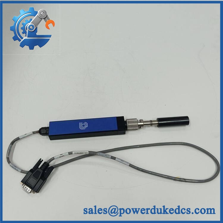
AMAT 0010-23715
Module 5: Migration, Compatibility & Installation Traps
Replacement Matrix
Replacement Classification: Drop-in Replacement Within the Matching AMAT PMAX Configuration
A like-for-like AMAT 0010-23715 replacement is appropriate when the installed tool uses the same PMAX emissometer architecture, probe mounting arrangement, connector configuration, and calibration baseline. The complete probe assembly should be matched rather than substituting an electrically similar temperature sensor.
0010-23715 → Different PMAX emissometer probe: Configuration Verification Required. Different probe assemblies may use different optics, cable configurations, or mounting arrangements even when they serve the same general measurement function.
0010-23715 → Generic pyrometer or temperature sensor: Hardware Modification Required. A conventional temperature sensor does not reproduce the emissivity-measurement function or the optical interface expected by the PMAX system.
⚠️ Field Traps — Watch Out
1. Optical contamination: Probe optics must remain clean and correctly aligned. Deposits on the optical path can change the measured emissivity signal and may appear as calibration drift rather than a complete sensor failure.
2. Cable and connector damage: Repeated thermal cycling can stress the probe cable and connector assembly. Inspect continuity, shielding, strain relief, and connector contacts before condemning the probe electronics.
3. Calibration mismatch: A replacement probe may require the correct PMAX calibration or equipment-specific parameter set. Do not assume that mechanically installing the assembly restores the original measurement accuracy automatically.
4. Process-dependent emissivity: Emissivity is influenced by wafer material, surface condition, temperature, and process history. A stable electrical signal does not by itself prove that the optical measurement is accurate.
Module 6: Quality Assurance SOP
Each AMAT 0010-23715 should undergo identification, mechanical, optical, electrical, and measurement verification before shipment.
- OEM identification visual inspection: Verify Applied Materials / AMAT markings, 0010-23715 part number, assembly labels, serial number where present, connector identification, and visible revision markings.
- Assembly verification: Confirm that the supplied item is the complete PMAX Emissometer RTP Probe Assembly, not a similar-looking probe, cable, or unrelated semiconductor-equipment component.
- Mechanical inspection: Examine the probe housing, optical window, mounting hardware, cable jacket, strain relief, connector, and any exposed fittings for cracks, deformation, corrosion, contamination, or thermal damage.
- Optical inspection: Inspect the measurement aperture and optical surfaces under appropriate clean conditions. Verify that no residue, scratches, or particulate contamination could affect the measurement path.
- Cable continuity test: Verify conductor-to-conductor continuity against the approved equipment wiring documentation and check for unintended shorts.
- Insulation verification: Where permitted by the equipment procedure, verify cable insulation and shield integrity using an appropriate low-risk test method that will not damage sensitive circuitry.
- Connector inspection: Check contact condition, pin alignment, locking mechanism, and mechanical retention.
- Power/interface verification: Connect the probe to an approved PMAX laboratory or service test configuration using the correct interface and confirm normal recognition.
- Signal verification: Apply an approved reference target or calibration source and verify that the emissometer produces a stable, repeatable measurement response.
- Measurement stability test: Repeat the reference measurement across multiple cycles and record repeatability, drift, and signal stability.
- Calibration verification: Compare the observed response against the applicable AMAT calibration procedure and record the calibration status where available.
- Temperature-response verification: Where the authorized test setup supports it, use controlled reference conditions to verify that the measurement response follows the expected process trend.
- Fault-response test: Simulate an approved disconnected-probe or signal-loss condition and verify the expected equipment diagnostic response.
- Extended stability test: Operate the probe assembly under representative environmental conditions while monitoring signal stability, cable integrity, connector behavior, and measurement repeatability.
- Final QC record: Retain complete part-number photographs, revision information, optical inspection results, continuity measurements, reference-target results, calibration observations, fault-response results, and final QC approval.
The AMAT 0010-23715 is identified as a PMAX Emissometer RTP Probe Assembly for Applied Materials rapid thermal processing equipment. Its primary function is optical emissivity measurement associated with wafer-temperature control, rather than conventional electrical temperature sensing.
For spare-parts control, the critical checks are the complete 0010-23715 identification, PMAX tool compatibility, probe mounting, optical condition, cable and connector integrity, calibration baseline, and equipment-specific configuration. Because detailed public specifications for this exact assembly are limited, fixed values such as optical range, wavelength, connector pinout, and calibration limits should be confirmed from the physical unit and applicable AMAT documentation before being published as certified specifications.











 Start Chat


