

Description
- Brand: Bently Nevada
- Full Model Number: 133396-01
- Lifecycle Status: Legacy / Limited-stock
- Core Function: 3500/53 Electronic Overspeed Detection I/O
- Top 3 Technical Specs: -24 VDC transducer supply, 40 mA max; 4–20 mA recorder output; 8.0 W typical consumption
- System: Bently Nevada 3500/53 Electronic Overspeed Detection System
- Module Type: Overspeed Detection I/O Module
- Transducer Compatibility: Bently Nevada 3300 8 mm, 3300 16 mm HTPS, 7200 series and magnetic pickup configurations
- Safety Architecture: 2oo2 or 2oo3 voting system support
- Environmental Sealing: Epoxy sealed
- Weight: Approx. 0.45 kg
- Stock & Condition: Exact stock confirmation required; New Surplus / Tested Refurbished; Emergency shipping subject to warehouse cutoff
Module 3: Obsolescence & Supply Chain Deep Dive
Overspeed protection is a shutdown-critical function, so a failed 133396-01 creates a very different procurement risk from an ordinary monitoring card.
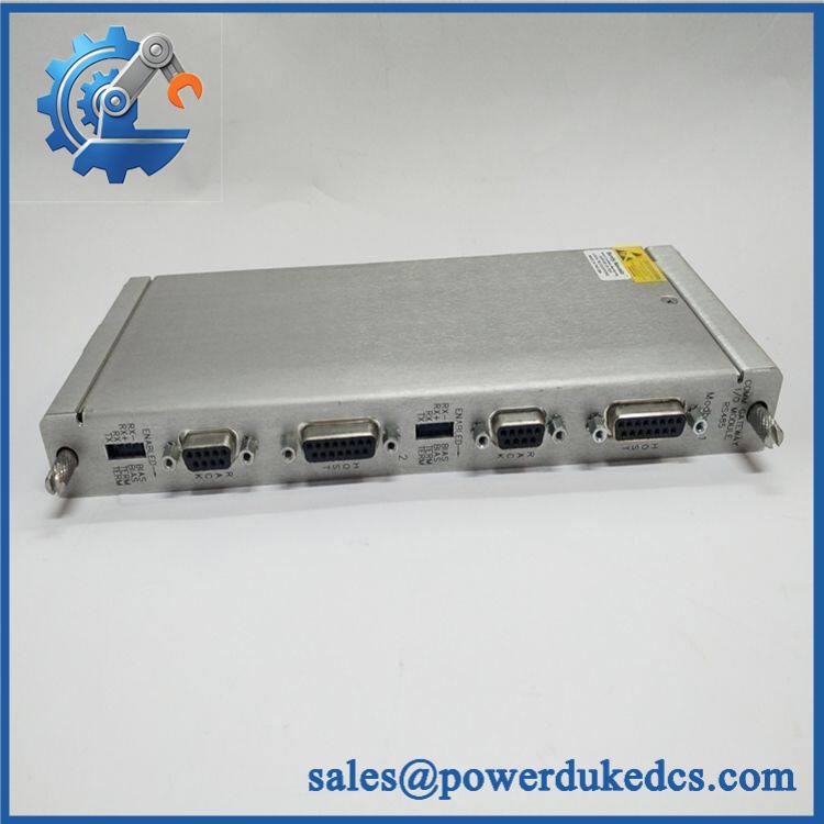
BENTLY 133396-01 3500/53
Published specifications identify an 8 W typical power draw, a -24 VDC transducer supply rated to 40 mA maximum, and a 4–20 mA recorder output.
The TCO argument is strong when the existing 3500/53 installation remains serviceable. Replacing the I/O module can preserve the installed rack, transducers, voting architecture, wiring, and shutdown philosophy instead of triggering a larger protection-system replacement. The 3500/53 can be configured for 2-out-of-2 or 2-out-of-3 voting, with 2oo3 commonly specified for higher availability, so procurement must match the replacement to the existing safety architecture. (For an overspeed protection circuit, a low-cost but incorrect module is far more expensive than a correctly tested spare.)
Module 4: Compatibility & Replacement Matrix
| Approval Item | Engineering Assessment |
|---|---|
| Exact Part Replacement | Drop-in Replacement when the installed I/O module is 133396-01 and the 3500/53 configuration matches |
| Software Compatibility | Configuration-dependent; verify 3500/53 system setup and voting architecture |
| Firmware Flash | Potentially required at system level if the installed firmware generation differs; verify before commissioning |
| Hardware Modification | Normally none for an exact-match replacement |
| Estimated Physical Swap | 30–90 minutes for qualified machinery-protection technicians |
| Engineering / Commissioning Allowance | 500–1,500 planning range |
| Post-Replacement Testing | Mandatory for overspeed input, alarm, recorder, and voting functions |
| Safety Impact | High — equipment should not return to normal operation until the protection path is functionally verified |
⚠️ Field Traps — Watch Out
- Voting Architecture: Do not commission a replacement without confirming whether the installed system uses 2oo2 or 2oo3 voting. The 3500/53 architecture supports both, and the replacement must be tested within the actual site arrangement.
- Transducer Type and Supply: Verify the installed pickup type and associated -24 VDC / 40 mA maximum transducer supply requirements. An apparently correct 3500/53 module can still produce a field problem if the transducer arrangement is mismatched.
Module 5: Quality Assurance & Testing SOP
- OEM anti-counterfeit visual inspection — verify Bently Nevada markings, 133396-01 identification, labels, connectors, PCB construction, epoxy sealing, and manufacturing traceability.
- Full part-number verification — record the complete 133396-01 identifier and all visible revision information.
- Mechanical inspection — examine the rack connector, terminal interfaces, mounting hardware, board edges, and enclosure for damage.
- PCB condition inspection — check for corrosion, contamination, cracked solder joints, damaged traces, overheating, and unauthorized rework.
- Electrical pre-screening — verify continuity, isolation, grounding, and supply-path integrity before energization.
- Power-on self-test (POST) — install the module in an approved 3500/53 test rack and verify normal initialization.
- Status LED verification — confirm expected OK, communication, bypass, test-mode, and alarm indications for the applicable module configuration.
- Tachometer input simulation — apply controlled speed/frequency signals representative of the installed transducer arrangement and verify correct speed detection.
- Overspeed trip simulation — progressively apply simulated overspeed conditions and verify the configured detection and trip response without exposing connected machinery to an uncontrolled trip.
- Voting logic test — validate the installed 2oo2 or 2oo3 arrangement and confirm that individual channel faults produce the expected diagnostic behavior.
- Recorder output test — verify the 4–20 mA output tracks the applicable full-scale speed range.
- Transducer supply test — verify the -24 VDC supply and maximum permitted current against the applicable system configuration.
- Extended energized run — monitor diagnostics, communication, speed readings, output stability, and thermal behavior for intermittent faults.
- Final QC release — retain identification photographs, test results, serial/traceability data, and ESD-safe packaging records.
The 3500/53 documentation identifies 133396-01 as the I/O component for the Electronic Overspeed Detection System and lists a dedicated firmware IC in the system’s spare-parts structure. That makes hardware revision and firmware verification worthwhile during QC rather than relying on a basic power-up test.
Module 6: Procurement & Lifecycle FAQ
Q1. Is BENTLY 133396-01 genuinely in stock, and what is the cutoff for emergency shipping?
Exact availability should be confirmed against 133396-01, quantity, condition, and destination before the PO is released. Current industrial listings show this part as available from some suppliers, while others describe it as limited-stock or discontinued, so emergency availability must be confirmed directly before dispatch.
Q2. How do you verify the condition and authenticity of an obsolete 133396-01?
Require complete part-number inspection, OEM marking verification, PCB and connector examination, electrical screening, powered 3500/53 testing, tachometer-input simulation, overspeed-trip simulation, voting verification, and 4–20 mA output testing. The unit should remain traceable to its QC record.
Q3. Are there firmware compatibility issues engineers should check before issuing the PO?
Yes. The 3500/53 system documentation identifies 134129-01 as a firmware IC spare, so the installed firmware generation should be recorded before replacing a legacy module. Confirm the module revision, firmware arrangement, system configuration, and voting architecture before commissioning.
Q4. Can 133388-01 replace 133396-01?
No, not automatically. The documented 3500/53 spare-parts structure distinguishes 133388-01 as the Overspeed Detection Module and 133396-01 as the Overspeed Detection I/O Module. They perform different functions within the system and should not be treated as interchangeable.
Q5. What warranty and return terms should procurement require?
Require a written warranty period, DOA criteria, return-authorization procedure, serial/part-number traceability, and exclusions for incorrect installation or electrical overstress. For a safety-critical overspeed component, the quotation should explicitly identify the 133396-01 configuration and tested condition.











 Start Chat


