

Description
- Brand: Bently Nevada
- Full Model Number: 3500/34 125696-01
- Lifecycle Status: Legacy / Mature 3500 Series hardware
- Core Function: Triple Modular Redundant Relay Module
- Top 3 Technical Specs: 4 relay channels; 3 independent relays per channel; 2oo3 voting architecture
- System: Bently Nevada 3500 Machinery Protection System
- Module Type: TMR Relay Module
- Relay Output Channels: 4
- Relay Architecture: Three independent relay paths per channel
- Associated I/O: 125704-01 TMR Relay I/O Module
- Agency Configuration: 3500/34-01-00 for no approvals required
- Application: High-reliability alarm, trip, shutdown, and interlock circuits
- Stock & Condition: Exact stock confirmation required; New Surplus / Tested Refurbished; Emergency shipping subject to cutoff
The Bently Nevada 3500/34 is the TMR Relay Module for applications requiring high-reliability relay voting. The documented assembly uses two half-height relay-monitor sections together with a full-size TMR relay I/O module, with three independent relays driving each of four relay outputs. The architecture supports 2-out-of-3 voting when used with the appropriate TMR rack arrangement.
Module 3: Obsolescence & Supply Chain Deep Dive
A failed 3500/34 125696-01 affects a shutdown or interlock path rather than simply removing a monitoring display. The module is designed for high-reliability applications where a single hardware fault should not create a false trip. Bently Nevada’s technical documentation describes the 3500/34 as a TMR relay module using three independent relay paths for each of four channels; the TMR relay I/O module provides the external contact interface.
From a TCO perspective, replacing the matched TMR relay assembly preserves the installed 3500 TMR rack, relay logic, field wiring, and shutdown architecture. A complete protection-platform replacement would add configuration migration, wiring changes, testing, outage coordination, and revalidation costs that are difficult to justify when the failure is isolated to the relay hardware. The engineering caveat is significant, though: the 3500/34 depends on a TMR Rack Interface Module and three appropriately configured monitor modules, so the replacement must be validated within the full TMR architecture rather than tested as an isolated relay card.
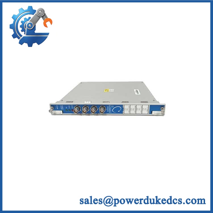
BENTLY 3500/34 125696-01
Module 4: Compatibility & Replacement Matrix
| Approval Item | Engineering Assessment |
|---|---|
| Exact Part Replacement | Drop-in Replacement when the existing installation is a matching 3500/34 TMR configuration |
| Software Compatibility | Configuration-dependent; verify TMR monitor grouping and relay Alarm Drive Logic |
| Firmware Flash | Potentially applicable at module level; the documented spare structure identifies firmware IC 132317-01 |
| Hardware Modification | Normally none for an exact replacement |
| Relay Channels | 4 independent output channels |
| Voting Architecture | TMR / 2oo3 |
| Relay Construction | 3 independent relays per output channel |
| Associated I/O | 125704-01 TMR Relay I/O Module |
| Estimated Physical Swap | 1–2 hours for qualified machinery-protection personnel |
| Engineering / Commissioning Allowance | 500–1,500 planning range |
| Post-Replacement Testing | Mandatory for all four channels and the complete TMR voting path |
The maintenance manual states that a 3500/34 TMR Relay Module consists of two half-height modules and one full-size I/O module, with triplicate relay circuitry providing the redundant relay functions. It also identifies 125696-01 as the TMR Relay Module spare and 125704-01 as its TMR Relay I/O Module spare.
⚠️ Field Traps — Watch Out
- TMR Architecture Mismatch: A 3500/34 is not equivalent to a conventional 3500/32 or 3500/33 relay module. The TMR relay requires the appropriate TMR rack architecture, including a TMR RIM and correctly configured monitor groups.
- Relay Logic / Fail-Safe State: The TMR I/O contacts are arranged for the intended relay-voting architecture. Preserve the existing Normally Energized arrangement and field termination scheme; do not change contact wiring based only on a visual match.
Module 5: Quality Assurance & Testing SOP
- OEM anti-counterfeit visual inspection — verify Bently Nevada identification, 125696-01 part marking, faceplate legends, connector arrangement, PCB construction, and traceability.
- Assembly verification — confirm the supplied hardware corresponds to the 3500/34 TMR arrangement and identify the associated 125704-01 I/O assembly where included.
- Hardware-generation audit — record visible revision information and verify compatibility with the installed TMR rack generation.
- Mechanical inspection — examine card guides, connectors, mounting hardware, module interfaces, and I/O terminals for deformation, corrosion, or prior repair.
- PCB condition inspection — check for damaged traces, cracked solder joints, contamination, overheating, and unauthorized rework.
- Electrical pre-screening — verify continuity, isolation, grounding, and relay-contact integrity before energization.
- Power-on self-test (POST) — install the module in an approved 3500 TMR test rack and verify normal initialization and module-status indications.
- Relay-channel testing — independently verify all four output channels and the associated triplicate relay paths.
- 2oo3 voting simulation — apply controlled alarm conditions to the redundant monitor inputs and verify correct 2-out-of-3 voting behavior.
- Single-fault injection test — simulate one failed relay or monitor path and verify that the remaining two paths maintain the intended output state.
- Alarm Drive Logic test — reproduce representative Alert, Danger, Not-OK, and configured logic conditions and verify the correct relay response.
- Contact-state verification — confirm the specified Normally Energized behavior and verify each external contact path with controlled continuity/load testing.
- Rack communication test — verify communication between the TMR relay module, TMR RIM, and associated monitor modules.
- Configuration-retention test — perform a controlled power cycle and confirm that relay assignments and system configuration remain correct.
- Extended operating test — monitor relay stability, diagnostics, communication status, and abnormal thermal behavior.
- Final QC release — photograph the identification, retain relay/voting test records, document the exact assembly supplied, and use ESD-safe packaging.
The documented maintenance procedure explicitly provides relay-verification steps using the 3500 rack configuration software and test signals to place selected monitor channels into alarm states. That makes 2oo3 voting verification and fault simulation central acceptance tests for a 3500/34.
Module 6: Procurement & Lifecycle FAQ
Q1. Is BENTLY 3500/34 125696-01 genuinely in stock, and what is the cutoff for emergency shipping?
Exact stock should be confirmed against 3500/34 125696-01, including whether the requirement is for the complete TMR relay assembly or the individual spare module. Current industrial listings report stock for this part, but inventory claims vary by supplier, so emergency dispatch should be confirmed against physical inventory and the daily shipping cutoff.
Q2. How do you verify the condition and authenticity of an obsolete or surplus 125696-01?
Require OEM marking verification, exact part-number inspection, PCB and connector examination, electrical screening, powered TMR-rack testing, relay-by-relay verification, 2oo3 voting tests, single-fault simulation, and contact-state checks. The individual relay assembly and associated I/O should remain traceable to the QC record.
Q3. Are there firmware compatibility issues engineers should check before issuing the PO?
Yes. The documented spare-parts structure identifies firmware IC 132317-01 for the 3500/34, so the installed hardware and firmware generation should be recorded before replacement. More importantly, confirm the TMR RIM, monitor grouping, relay logic, and rack configuration before commissioning.
Q4. Can 3500/32 or 3500/33 relay modules replace 3500/34 125696-01?
No, not as a direct substitution for a TMR protection architecture. The 3500/32 is a conventional four-channel relay module, while the 3500/34 provides TMR relay voting with three independent relay paths per output channel. A standard relay module does not reproduce the same fault-tolerant architecture.
Q5. What warranty and return terms should procurement require?
Require a written warranty period, DOA criteria, return-authorization procedure, serial/part-number traceability, and exclusions for incorrect wiring, electrical overstress, or unauthorized changes to the TMR architecture. The quotation should explicitly state 3500/34 125696-01, the supplied assembly configuration, and the tested condition.











 Start Chat


