

Description
- Brand: Bently Nevada
- Full Model Number: 125720-01
- Lifecycle Status: Obsolete / Replacement Available
- Core Function: 3500/32 four-channel relay output I/O module
- Top 3 Technical Specs: 4 independently programmable relay outputs; SPDT relay contacts; -30°C to +65°C operating range
- Stock & Condition: Physical stock verification required; New Surplus / Tested Refurbished; Emergency dispatch subject to QA release
Module 3: Obsolescence & Supply Chain Deep Dive
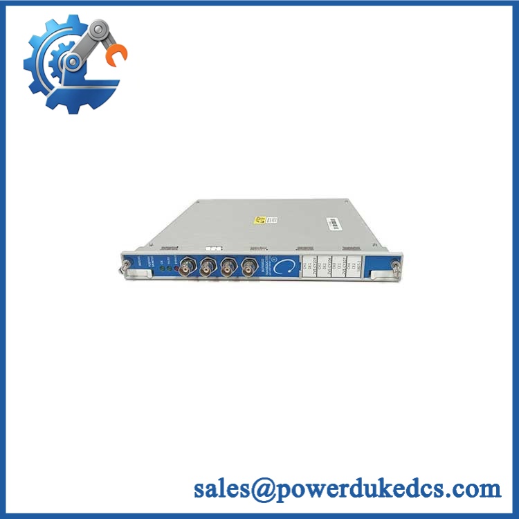
A failed Bently Nevada 125720-01 can interrupt relay-based alarm and shutdown interfaces even when the rest of the 3500 rack remains operational. The 125720-01 is the four-channel Relay Output I/O Module associated with the 3500/32 relay module. Each of its four relay outputs can be independently programmed through the 3500 Rack Configuration Software to implement alarm-drive and voting logic. Bently Nevada documentation identifies the 125720-01 as the I/O portion of the 3500/32 assembly, while current replacement information identifies 125720-02 for certain hazardous-area and functional-safety applications.
For an installed 3500/32 system, replacing the exact relay I/O assembly can be considerably less expensive than redesigning shutdown wiring, PLC interfaces, or the complete machinery-protection architecture. Existing 3500 monitor modules, relay logic, field wiring, and configuration files can remain in service when the correct I/O version is restored. The procurement issue is therefore configuration matching, not simply finding another four-channel relay card. —The 125720-01 is an older configuration that some suppliers now identify as discontinued, so physical verification and confirmation of the required replacement path should be completed before the PO is released.
Bently Nevada 125720-01 3500/32
Module 4: Compatibility & Replacement Matrix
| Replacement Scenario | Classification | Engineering / Procurement Guidance |
|---|---|---|
Exact 125720-01 replacing the same installed relay I/O |
Drop-in Replacement | Match complete part number, relay configuration, terminal arrangement, and 3500/32 application |
125720-01 with matching 3500/32 control module |
Hardware Compatible | Verify complete assembly and field termination arrangement |
125720-02 replacing 125720-01 |
Engineering Review Required | Current documentation associates 125720-02 with hazardous-area and functional-safety applications |
| Complete 3500/32 assembly using newer replacement components | Software Compatible / Hardware Verification Required | Confirm control module, I/O module, firmware, configuration, and agency requirements |
| Different 3500 relay module family | Hardware Modification | Requires review of relay logic, wiring, contact ratings, and cabinet configuration |
The 3500/32 architecture uses a separate relay control module and relay output I/O module. Current documentation identifies 125720-01 as the older spare I/O module, while 125720-02 is the replacement option for specified hazardous-area and functional-safety systems.
Estimated switch cost/time: With a verified spare already on-site, plan approximately 1–3 hours for controlled replacement, terminal verification, relay checkout, and functional testing. A newly sourced unit may require 1–5 business days for inspection and expedited transportation. These are planning estimates.
Field Traps — Watch Out
- 125720-01 vs. 125720-02: Current supplier documentation identifies
125720-02as the newer spare for hazardous-area and functional-safety systems. Do not substitute it without confirming the applicable agency and system requirements. - I/O module vs. control module:
125720-01is the rear relay I/O module, while the front control electronics are a separate component. A quote for only one section does not necessarily represent a complete 3500/32 relay module. - Relay logic retention: The four outputs are independently programmable and can use alarm-drive logic. Record the existing configuration before replacement.
- Contact-rating check: The relay contacts must be evaluated against the actual field load. Do not approve a replacement based only on channel count.
Module 5: Quality Assurance & Testing SOP
This module sits directly in the relay output path, so QA should verify both the electronics and the actual contact behavior under representative conditions.
- Part-number verification: Confirm
125720-01, revision, serial/traceability data, and Bently Nevada identification. - OEM anti-counterfeit visual inspection: Inspect manufacturer markings, PCB identifiers, relay components, connectors, terminal interfaces, and evidence of unauthorized rework.
- Physical condition inspection: Check the enclosure, terminal blocks, PCB, relay housings, connector contacts, and mounting features for corrosion, contamination, cracks, or thermal damage.
- Terminal inspection: Examine every field termination point for oxidation, looseness, damaged screws, bent contacts, or insulation displacement.
- Continuity testing: Verify applicable power, ground, and signal paths before energization.
- Power-on self-test (POST): Install the I/O module with a compatible 3500/32 control module and verify expected startup and module recognition.
- Status indication check: Verify the associated OK and communication indications during normal operation.
- Four-channel relay testing: Exercise all four relay channels independently and confirm correct state changes.
- SPDT contact verification: Test normally open and normally closed contacts for every relay and record continuity in each state.
- Coil/relay operation test: Verify reliable pickup and dropout behavior across repeated switching cycles.
- Alarm-drive logic test: Apply simulated monitor alarm inputs and confirm each programmed output responds according to the approved logic.
- Voting logic test: Where configured, test AND/OR voting combinations across representative monitor channels.
- Field-load simulation: Apply representative resistive or approved simulated loads within the relay contact rating and monitor contact stability.
- I/O load testing: Operate multiple relay channels simultaneously while observing supply stability, contact behavior, and thermal condition.
- Communication test: Verify that the associated 3500/32 control module exchanges the expected control and status information with the rack.
- Configuration verification: Compare programmed relay logic against the approved site configuration before release.
- Extended observation: Repeatedly cycle the relay outputs under representative operating conditions to detect intermittent contacts or communication faults.
- Final QC release: Record part number, revision, relay test results, contact-state results, configuration verification, photographs, condition grade, test date, and QC authorization.
Published technical information identifies the 3500/32 relay module as a four-channel relay system, with individually programmable outputs and alarm-drive logic. One current spare-parts record lists approximately 6 W typical power consumption and a -30°C to +65°C operating range for the module family.
Module 6: Procurement & Lifecycle FAQ
Q1. Is the Bently Nevada 125720-01 genuinely in stock, and what is the cutoff for emergency shipping?
Physical inventory should be verified against the exact 125720-01 part number before the PO is accepted. Current supplier records are mixed: some list inventory, while others classify the part as discontinued or repair-only. The actual physical unit should therefore be identified and QA-released before a firm emergency-shipping commitment is made.
Q2. How do you guarantee the condition and authenticity of an obsolete 125720-01?
Require exact part-number verification, OEM visual inspection, terminal inspection, controlled power-up, four-channel relay testing, contact-state verification, alarm-logic testing, and documented QC results. For surplus or refurbished stock, retain photographs of the actual module and all identification markings.
Q3. Can 125720-02 replace 125720-01?
Potentially, but it should not be approved as a universal substitution. Current documentation identifies 125720-02 as the spare relay output module for hazardous-area and functional-safety systems, while 125720-01 is the older configuration. The installed agency and functional-safety requirements must be checked first.
Q4. Are firmware compatibility issues something engineers should check before issuing the PO?
Yes, at the complete 3500/32 assembly level. The relay I/O module itself is not normally treated as the primary firmware-bearing component, but the associated relay control module and rack configuration determine the programmed alarm-drive logic. Preserve the existing configuration before replacement and verify it after installation.
Q5. What warranty and return terms should be written into the PO?
Specify warranty duration, DOA coverage, relay contact performance, alarm-logic conformity, return authorization, inspection period, and serial-number traceability. For refurbished inventory, require the actual four-channel relay test record and define whether failures discovered during commissioning are covered.











 Start Chat


