

Description
- Brand: Bently Nevada
- Full Model Number: 1900/55
- Lifecycle Status: Obsolete / Replacement available
- Core Function: Four-channel low-frequency fan vibration monitor
- Top 3 Technical Specs: 4 vibration channels; fan gearbox monitoring; 1.5–1000 Hz response with 190501 Velomitor CT
- Stock & Condition: New Surplus / Tested Refurbished; Physical stock confirmation required; Emergency dispatch subject to order cutoff
The Bently Nevada 1900/55 Fan Monitor is a four-channel monitor intended for low-frequency vibration monitoring on fan gearboxes. The operation manual specifies that the 190501 Velomitor CT is required for low-frequency applications, with a stated response of 1.5 to 1000 Hz ±3 dB and suitability for fan speeds of 90 RPM or greater.
Module 3: Obsolescence & Supply Chain Deep Dive
A failed 1900/55 can remove both condition monitoring and protective functions from a fan application, turning a relatively small instrumentation failure into a maintenance outage. The unit continuously monitors four vibration channels and provides configurable alarm-relay functions through its front-panel controls. Its design is aimed specifically at low-frequency fan machinery, so substituting a generic vibration monitor can require changes to transducers, signal scaling, alarm logic, and plant wiring.
The lifecycle issue is more significant now because Bently Nevada documents the 1900/65A as an upgrade or replacement for the 1900/55. The official replacement procedure requires removing the 1900/55, transferring the existing wires to new terminal blocks, installing a retrofit panel and 35 mm DIN rail, then creating a new configuration using the 1900/55 template in the 1900/65A software. When an exact 1900/55 is available and the site needs the existing installation restored quickly, that can reduce migration engineering and downtime compared with performing the documented 1900/65A retrofit immediately.
Module 4: Compatibility & Replacement Matrix
| Purchase Approval Item | Assessment |
|---|---|
| Replacement Classification | Drop-in Replacement for an existing 1900/55 |
| System Family | Bently Nevada 1900 Series |
| Monitoring Configuration | Four-channel fan vibration monitoring |
| Software Compatibility | Existing 1900/55 configuration; verify communication-card and alarm setup |
| Hardware Modification | Normally not required for exact 1900/55 replacement |
| Estimated Physical Changeover | 1–3 hours |
| Commissioning / Validation | Required for transducer, alarm, relay, and display verification |
| Alternative Lifecycle Path | 1900/65A documented upgrade/replacement |
Field Traps — Watch Out
- Transducer selection: For low-frequency applications, the operation manual specifically requires the 190501 Velomitor CT and states a response of 1.5–1000 Hz ±3 dB. A different sensor can materially change the measurement response.
- 1900/65A is not a simple firmware swap: The documented migration requires terminal-block transfer, a retrofit panel, DIN rail installation, and a new configuration based on the 1900/55 template. Treat it as a hardware/configuration migration rather than a direct electronics substitution.
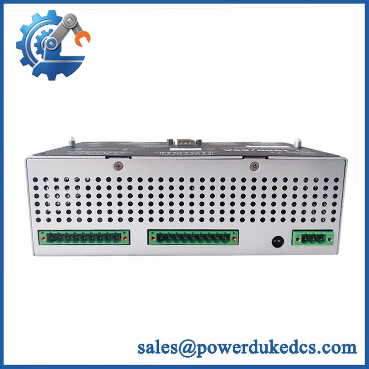
Bently Nevada 1900/55
Module 5: Quality Assurance & Testing SOP
The 1900/55 should be tested as a complete monitoring instrument, with particular attention to its four vibration channels and relay behavior.
- Incoming traceability: Record Bently Nevada markings, complete 1900/55 identification, serial number, configuration code, revision, and available date-code information.
- OEM anti-counterfeit visual inspection: Inspect enclosure, labels, terminal blocks, display/control panel, PCB markings, connectors, and evidence of unauthorized repair.
- Mechanical inspection: Check housing, mounting points, terminal interfaces, enclosure hardware, and front-panel controls.
- Power-on self-test (POST): Apply the specified supply and verify normal startup, display operation, and diagnostic status.
- Supply verification: Confirm correct operating voltage and inspect for abnormal current draw or heating.
- Four-channel input testing: Apply controlled vibration signals to all four channels and verify correct displayed values.
- Frequency-response test: Where laboratory equipment permits, verify response through the application band relevant to fan monitoring.
- Alarm verification: Test programmable alarm thresholds, relay delays, latching/non-latching behavior, and relay state changes.
- Relay output test: Verify alarm and danger relay operation under simulated fault conditions.
- Communication-card test: Where installed, verify data transmission to the connected plant computer or monitoring system.
- Configuration verification: Record point IDs, engineering units, measurement parameters, and configured delays before shipment.
- Extended operation: Run the monitor continuously with representative signals and check channel stability.
- Final QC release: Record configuration code, serial number, test results, alarm/relay results, inspection date, and technician approval.
Module 6: Procurement & Lifecycle FAQ
1. Is the Bently Nevada 1900/55 genuinely in stock, and what is the cutoff for emergency shipping?
Current supplier listings show mixed availability. One listing currently advertises a 1900/55-01-01-01-00 configuration as in stock, while another listing shows a more detailed 1900/55 configuration as available with a stated one-year warranty. For an emergency order, confirm the exact configuration code, physical stock, condition, and same-day shipping cutoff before issuing the PO.
2. How do you verify the condition and authenticity of an obsolete 1900/55?
Identification should include the complete configuration code, serial number, front-panel markings, enclosure, terminal blocks, PCB construction, and communication-card configuration where fitted. Functional testing should then cover all four vibration inputs, display response, alarm logic, and relay operation. Retain photographs and test records with the asset file.
3. Are there any firmware compatibility issues engineers should check before issuing the PO?
The more important issue is configuration compatibility. Confirm the exact 1900/55 ordering/configuration code, sensor type, alarm settings, relay logic, measurement units, point IDs, and communication-card arrangement. The monitor’s programmable options include relay timing, relay latching, relay energization state, LCD scan time, measurement units, and point ID.
4. Can the 1900/55 be replaced without modifying the cabinet?
Yes, for an exact 1900/55 replacement in the existing installation, the objective is normally to preserve the existing wiring and mounting arrangement. A transition to the newer 1900/65A, however, requires the documented retrofit process, including new terminal blocks, a retrofit panel, DIN rail installation, and configuration transfer.
5. What warranty and return terms should procurement require?
The PO should specify the complete 1900/55 configuration code, condition, tested functions, warranty period, and return procedure. Warranty coverage should address DOA and verified monitoring or relay failures while excluding damage from incorrect supply voltage, field wiring errors, transducer faults, environmental damage, and unauthorized configuration changes.











 Start Chat


