

Description
- Brand: Bently Nevada
- Full Model Number: 3500/34
- Lifecycle Status: Legacy / Supported 3500 Series
- Core Function: Triple Modular Redundant relay logic for high-availability machinery protection
- Top 3 Technical Specs: TMR architecture; 2-out-of-3 voting; Three independent relays driving a single relay output
- Stock & Condition: Physical stock verification required; New Surplus / Tested Refurbished; Emergency dispatch subject to QA release
Module 3: Obsolescence & Supply Chain Deep Dive
A failed Bently Nevada 3500/34 creates a different procurement problem from a standard relay card because the 3500/34 is part of a Triple Modular Redundant (TMR) protection arrangement. Bently Nevada documentation describes the 3500/34 as a TMR Relay Module using three independent relay paths to drive a single output and working with a TMR Rack Interface Module plus three monitor modules configured as a TMR set. The assembly therefore has system-level dependencies that must be checked before a replacement is approved.
For an installed TMR protection system, restoring the original relay architecture can be substantially less expensive than redesigning the trip logic around a different protection platform. Existing monitor modules, voting logic, rack wiring, and shutdown interfaces can remain in place when the replacement configuration is correctly matched. That limits engineering hours, shutdown testing, and commissioning work. —Procurement should note that 3500/34 identifies the TMR relay function, while the relay I/O assembly has its own part number, so a PO should not be released from the 3500/34 designation alone when a complete assembly or replacement I/O module is required. Bently Nevada’s field-wiring documentation identifies 125704-01 as the TMR Relay I/O module.
Module 4: Compatibility & Replacement Matrix
| Replacement Scenario | Classification | Engineering / Procurement Guidance |
|---|---|---|
Exact 3500/34 TMR relay configuration replacing the installed assembly |
Drop-in Replacement — subject to configuration verification | Confirm monitor set, TMR rack arrangement, relay I/O, and wiring |
| Same 3500/34 configuration with matching relay I/O | Hardware Compatible | Verify the associated TMR RIM and three-monitor voting arrangement |
| Standard 3500/32 relay module replacing 3500/34 | Hardware Modification | Standard and TMR relay architectures have different voting arrangements |
| Different TMR relay I/O configuration | Engineering Review Required | Verify terminal layout, relay outputs, voting logic, and field wiring |
| Migration to another shutdown/protection platform | Hardware Modification | Requires system-level design, wiring changes, logic validation, and commissioning |
Estimated switch cost/time: For an exact tested replacement already staged on-site, plan approximately 2–6 hours for controlled removal, module installation, relay/I/O verification, TMR logic checkout, and trip-path testing. A sourced replacement may add 1–5 business days for inspection and expedited transport. These are planning estimates.
Field Traps — Watch Out
- TMR vs. standard relay architecture: The 3500/34 uses a TMR arrangement with 2-out-of-3 voting, while the 3500/32 is a conventional four-channel relay module. Do not substitute between them without a protection-logic review.
- Relay I/O part-number confusion:
3500/34is the module function designation; Bently Nevada documentation identifies 125704-01 as the associated TMR Relay I/O module. Confirm whether the buyer needs the complete relay module, the I/O assembly, or both. - Three-monitor dependency: The TMR relay arrangement works with three monitor modules configured as a redundant set. A missing or incorrectly configured monitor can affect the intended voting architecture.
- Trip-path verification: Do not return the rack to service after a simple continuity check. The complete alarm/trip chain should be tested through the actual TMR logic.
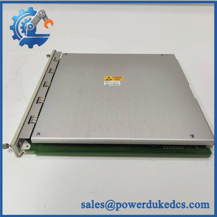
Bently Nevada 3500/34
Module 5: Quality Assurance & Testing SOP
The 3500/34 should be qualified as a protection-system component. Relay actuation and voting behavior require functional testing under controlled conditions.
- Part-number verification: Confirm
3500/34, associated module identification, revision, serial/traceability information, and the required TMR Relay I/O part number. - OEM anti-counterfeit visual inspection: Inspect Bently Nevada markings, PCB identifiers, relays, connectors, terminal assemblies, module construction, and evidence of unauthorized rework.
- Physical condition inspection: Check the housing, edge connectors, relay assemblies, mounting hardware, terminal contacts, and PCB surfaces for corrosion, impact, contamination, or thermal damage.
- Relay inspection: Examine each independent relay path for signs of contact wear, overheating, arcing, or mechanical damage.
- I/O configuration verification: Confirm the installed TMR Relay I/O configuration and terminal arrangement before energization.
- Continuity testing: Verify applicable power, ground, signal, and relay contact paths.
- Power-on self-test (POST): Install the assembly in a compatible 3500 rack and verify normal startup and module recognition.
- Status indication check: Verify the expected OK, communication, and alarm-related status indications under normal operation.
- Independent relay testing: Exercise each relay path separately and record pickup/dropout behavior.
- 2-out-of-3 voting test: Simulate the required alarm conditions across the three redundant inputs and verify the expected TMR voting response.
- Single-channel fault test: Simulate one failed or unavailable monitor path and confirm the remaining architecture behaves according to the configured voting scheme.
- Alarm logic testing: Apply controlled alarm and danger conditions and verify relay response.
- Trip-output testing: Verify the final relay output path to the shutdown interface using a controlled load or approved simulation.
- Reset testing: Confirm expected reset and recovery behavior following an alarm/trip simulation.
- I/O load testing: Operate relay contacts under a representative test load while monitoring contact stability and thermal behavior.
- Communication test: Verify rack communication with the associated TMR Rack Interface Module where applicable.
- Extended observation: Repeatedly cycle representative alarm and reset conditions to identify intermittent relay or contact faults.
- Final QC release: Record complete identification, I/O configuration, relay test results, voting results, photographs, condition grade, test date, and QC authorization.
Bently Nevada’s documentation describes the 3500/34 as consisting of two half-height monitors and one full-size I/O module, with the I/O module containing the triplicate relays and associated control logic. That assembly structure should be checked during receiving inspection when a complete 3500/34 configuration is being supplied.
Module 6: Procurement & Lifecycle FAQ
Q1. Is the Bently Nevada 3500/34 genuinely in stock, and what is the cutoff for emergency shipping?
Physical inventory should be verified against the actual 3500/34 assembly and its associated I/O hardware before the PO is accepted. Emergency dispatch depends on QA completion, warehouse location, carrier pickup time, and destination. Same-day shipment should only be confirmed after the required TMR components have been physically identified and released.
Q2. How do you guarantee the condition and authenticity of a 3500/34?
Require OEM visual inspection, exact configuration verification, PCB and connector inspection, relay-contact testing, alarm simulation, TMR voting tests, trip-output verification, and documented QC results. The test record should clearly identify which relay paths and I/O assemblies were tested.
Q3. Does 3500/34 require firmware compatibility checks?
Yes, but the main concern is the complete 3500 rack configuration, not simply the relay contacts. Record the installed monitor types, firmware revisions where applicable, rack configuration, TMR RIM, relay I/O configuration, and 3500 Rack Configuration Software settings before replacement.
Q4. Is 3500/34 the same as 125704-01?
No. 3500/34 identifies the TMR Relay Module, while 125704-01 is identified as the corresponding TMR Relay I/O assembly in Bently Nevada field-wiring documentation. Procurement should state exactly which hardware is required.
Q5. What warranty and return terms should be written into the PO?
Specify warranty duration, DOA coverage, relay-operation coverage, TMR voting-function coverage, I/O conformity, return authorization, inspection period, and serial-number traceability. For refurbished inventory, require the actual relay and voting test record and define whether failures discovered during commissioning are covered.











 Start Chat


