

Description
- Brand: ALSTOM
- Full Model Number: CMP1838
- Associated References: TRVCO62345000 / CP00005202
- System/Series Family: ALSPA MV3000 drive/control system
- One-Sentence Core Function: Analog-output control board used within the ALSPA MV3000 control architecture
- Top 3 Hardcore Specs: CMP1838 control board; TRVCO62345000 assembly reference; CP00005202 part reference
- Stock Status: New Surplus / Fully Tested Refurbished — verify PCB revision, host drive, and exact I/O configuration before shipment
Module 3: Technical Product Introduction
A control-board fault inside a legacy ALSPA MV3000 installation can stop a drive sequence even when the power stage and field wiring remain intact. The ALSTOM CMP1838, identified with TRVCO62345000 and CP00005202, is listed in industrial spare-parts records as an analog-output/control board associated with the ALSPA MV3000 family. Current industrial catalogs also place CMP1838 specifically within the MV3000 control-board product group.
The exact electrical specification should be treated as configuration-dependent. Public records consistently identify the three references together, but they do not provide a sufficiently authoritative OEM datasheet establishing channel count, output-current range, resolution, supply voltage, or connector pinout for this exact assembly. That is important during migration: a supplier-generated description may identify CMP1838 as a control board or analog-output card, but the installed drive’s engineering drawings and the physical PCB markings must determine the final replacement criteria.
Module 4: Application Scenarios & Field Realities
- Inside an ALSPA MV3000 drive cabinet, CMP1838 is used as a control-board assembly within the drive’s electronic control structure. When a drive exhibits an output-control fault, inspect the board, mating backplane/connectors, and associated I/O paths before replacing power semiconductors or the complete drive assembly.
- For analog control channels, verify the actual signal destination before replacement. An analog-output designation does not, by itself, establish whether a given installation uses voltage, current, bipolar, or unipolar signaling. The cabinet schematic should remain the controlling document.
- During brownfield drive refurbishment, retain all three identification strings: , TRVCO62345000, and CP00005202. Those references appear together in multiple industrial records and materially reduce the risk of receiving a visually similar board with a different hardware build.
- Where the board is being held as a critical spare, record the host-drive model and PCB revision with the inventory item. —The same base designation should not be assumed interchangeable across unidentified cabinets without checking revision and system documentation.
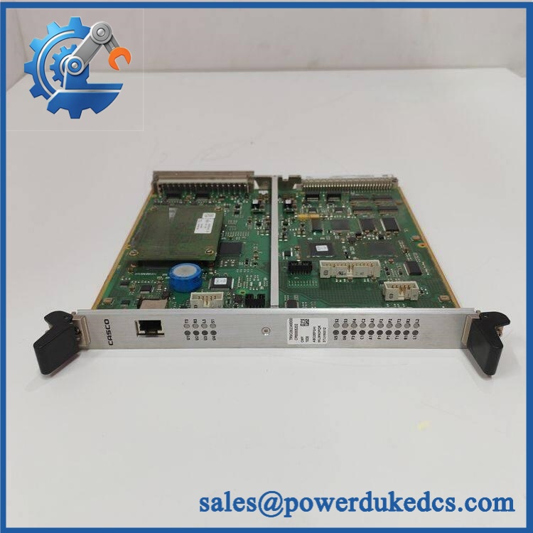
ALSTOM CMP1838 TRVCO62345000 CP00005202
Module 5: Migration, Compatibility & Installation Traps
Replacement Matrix
| Replacement Type | Assessment |
|---|---|
| Drop-in Replacement | Conditional — suitable only when , TRVCO62345000, CP00005202, PCB revision, host drive, and interface arrangement match |
| Software Compatible | Conditional — verify drive firmware, parameter set, control configuration, and board revision |
| Hardware Modification Required | Normally no for an exact like-for-like replacement; connector, backplane, I/O configuration, and host-drive revision must match |
⚠️ Field Traps — Watch Out
1. Do not rely on the base number alone.
The complete identity is CMP1838 / TRVCO62345000 / CP00005202. Industrial records consistently associate these references, and retaining the complete string is the safest way to control the spare.
2. Do not invent analog-output specifications.
Some commercial records classify the unit as an AO card, while another describes it broadly as a plug-in control/processor module. Public evidence does not establish a trustworthy channel count or exact analog output range. Those values should be taken from the physical board and applicable ALSPA documentation.
3. Verify the host hardware revision.
A replacement board that physically mates with the rack can still fail at commissioning if the firmware, configuration, connector assignment, or control-board revision differs from the original installation.
4. Inspect the backplane before condemning the replacement.
A contaminated or mechanically damaged backplane connector can create intermittent control faults that look like a defective . Check contact condition and insertion depth during installation.
Module 6: Quality Assurance SOP
- OEM anti-counterfeit visual inspection — inspect ALSTOM identification, marking, reference, CP00005202 reference, PCB labels, connector construction, and manufacturing identifiers.
- Exact part-number verification — confirm against the purchase order and physical board.
- Host-system verification — confirm the intended equipment is an installation and record the host drive model and cabinet position.
- Revision record — photograph and record PCB revision, serial number, firmware identifiers, assembly codes, and all visible configuration markings.
- Mechanical inspection — inspect backplane connectors, edge contacts, mounting hardware, board guides, heat-sensitive components, and PCB surfaces for oxidation, contamination, cracks, or impact damage.
- Power-on self-test (POST) — energize the board only in a compatible test environment and record startup behavior, diagnostic indications, current draw, and abnormal temperature rise.
- Control-board functional test — execute the approved diagnostic procedure and confirm that the control board reaches normal operating status.
- Analog-output simulation — where the applicable OEM documentation identifies the output channels and ranges, apply controlled simulated commands and measure the corresponding analog outputs with calibrated instrumentation.
- Channel verification — test every documented analog-output channel where the laboratory fixture supports the exact board configuration. Record commanded value, measured value, channel number, and diagnostic result.
- Backplane/I/O verification — verify stable data exchange between and the compatible control architecture. Check representative control and status signals through the actual system interface.
- Parameter/firmware verification — capture firmware revision, drive parameters, board identification, and applicable configuration data. Confirm compatibility before loading customer-specific parameters.
- Communication handshake verification — perform only the communications test supported by the confirmed architecture. Do not claim Ethernet, serial, or fieldbus compatibility without documentation for the installed configuration.
- Drive-level validation — where an approved test rig is available, verify the board under representative command conditions without connecting an uncontrolled motor load.
- Final QC and packaging — document exact identifiers, PCB revision, functional-test results, photographs, ESD protection, and packaging condition before shipment.
Engineering note: The supplied ALSTOM is consistently associated in current industrial records with the product family, and multiple records classify as a control/AO board. However, the public evidence does not establish a sufficiently authoritative channel count, analog output range, supply voltage, or pinout for this exact assembly. Those parameters should therefore be verified from the physical board and project documentation before being published as hard specifications.











 Start Chat


