

Description
- Brand: ABB
- Full Model Number: DATX110
- ABB Part Number: 3ASC25H209 / 3BSC980004R784
- System/Series Family: ABB ASTAT Crane Control System
- Core Function: I/O interface board for digital signal acquisition, output control, analog input, and pulse/encoder-related functions
- Top 3 Hardcore Specs: 17 digital inputs; 8 digital outputs; 11-bit + sign-bit analog input resolution
- Digital Input Supply: 110 V DC
- Digital Output: 8 channels
- Analog Input: Multiple configurable analog input channels
- Stock Status: New Surplus / Factory-Sealed or Fully Tested Refurbished subject to actual inventory condition
Available technical listings consistently associate DATX110, 3ASC25H209, and 3BSC980004R784 as the same ABB board designation. One detailed listing identifies it as an I/O board without analog output for the ASTAT crane control system, with digital I/O, analog input, and pulse-encoder interfaces.
Module 3: Technical Product Introduction
A DATX110 failure in an ASTAT crane controller can affect several signal paths at once. The board sits between the control electronics and field devices such as limit switches, brakes, contactors, operator controls, and motor-related feedback. ABB DATX110 3ASC25H209 3BSC980004R784 is documented as an I/O board associated with the ASTAT crane-control architecture. Available technical documentation identifies 17 digital inputs rated for 110 V DC, 8 digital outputs, analog input capability, and a pulse/encoder interface.
For maintenance planning, the important point is that this is not simply a generic digital I/O card. Its field interfaces are tied to the ASTAT control application. The available specification identifies 11-bit + sign-bit analog input resolution and digital signal response of up to approximately 10 ms. The same source describes compatibility with DARA-series control modules and fiber-optic expansion through associated cabin I/O equipment. These details should be verified against the exact ASTAT hardware revision installed at the site before a replacement is commissioned.
Module 4: Application Scenarios & Field Realities
- On large gantry and harbor cranes, DATX110 can handle the interface between the ASTAT control system and field devices used for hoisting, luffing, and slewing. Limit switches, brake commands, contactor status, and operator-control signals all require correct I/O assignment. A single wiring error can therefore affect a motion circuit rather than just one diagnostic point.
- During brake and limit-switch troubleshooting, the digital input section deserves particular attention. The documented DATX110 configuration includes 110 V DC digital inputs, so technicians should not treat these terminals like a 24 V PLC input bank. Verify the cabinet schematic and terminal voltage before probing the field wiring.
- For motor temperature and protection feedback, the analog input section can be part of the signal-acquisition chain. Before replacing the board, compare the measured field signal with the ASTAT parameter configuration; a board replacement will not correct an incorrect channel assignment or damaged external sensor.
- When synchronizing multiple crane drives, the board can participate in the signal exchange required by the ASTAT control architecture. Available documentation describes Master-Follower applications and fiber-optic expansion through additional I/O equipment. The exact topology, however, depends on the installed DARA/ASTAT configuration.
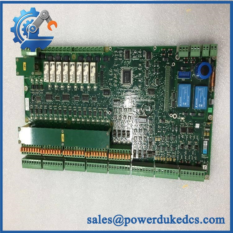
- ABB 3ASC25H209 3BSC980004R784
Module 5: Migration, Compatibility & Installation Traps
Replacement Matrix
| Replacement Case | Classification | Engineering Requirement |
|---|---|---|
| 3ASC25H209 3BSC980004R784 → identical | Drop-in Replacement | Verify part number, hardware revision, connectors, and ASTAT configuration |
| Same family with different hardware revision | Software/Configuration Verification | Confirm ASTAT Tool parameters and installed controller compatibility |
| Different ABB I/O board substituted for | Hardware Modification Required | Revalidate wiring, signal levels, channel assignment, control software, and I/O mapping |
| used outside its documented ASTAT architecture | Not automatically compatible | Obtain system-level engineering confirmation before installation |
Field Traps — Watch Out
1. Do not assume all digital inputs are 24 V DC.
Available technical information identifies the digital-input section as 110 V DC. Applying a 24 V assumption to the cabinet wiring can produce a false diagnostic conclusion. Confirm the actual terminal voltage from the ASTAT electrical drawings before testing.
2. Verify the complete part-number chain.
The same board is listed under , 3ASC25H209, and 3BSC980004R784. Because online descriptions for this part are inconsistent—some sources incorrectly describe it as a generic analog or communication module—the physical nameplate and ASTAT documentation should take precedence over a third-party description.
Installation note: Isolate the crane control cabinet according to the site’s electrical safety procedure before removing the board. Record the original connector positions and parameter configuration before replacement. For a working crane, perform functional checks at low-risk operating conditions before returning the equipment to normal service.
Module 6: Quality Assurance SOP
For ABB 3ASC25H209 3BSC980004R784, pre-shipment QA should verify both the physical board and its I/O behavior. Because the part is associated with crane motion control, the test record should be traceable to the exact board supplied.
- Part-number verification: Confirm , 3ASC25H209, and 3BSC980004R784 against the physical label and order record.
- OEM anti-counterfeit visual inspection: Check ABB markings, PCB identification, component layout, connectors, board finish, revision markings, and manufacturing labels.
- Mechanical inspection: Examine connectors, terminal areas, mounting points, PCB edges, and housing for cracks, corrosion, contamination, or impact damage.
- Power-on self-test (POST): Power the board through an appropriate ASTAT-compatible test setup and inspect available status indications and diagnostic information.
- Digital input verification: Exercise the applicable input channels using the correct test voltage and confirm that the controller registers the expected ON/OFF states.
- Digital output verification: Test the eight documented output channels with an appropriate controlled load. Confirm switching behavior and output status feedback where supported.
- Analog input verification: Apply calibrated test signals to the applicable analog channels and compare measured values with the configured reference. The documented resolution is 11-bit + sign bit.
- Encoder/pulse interface verification: Where the test setup supports it, verify pulse or encoder signal acquisition rather than limiting the inspection to digital I/O.
- Communication handshake verification: Confirm that the ASTAT control system recognizes the board and that the associated controller/I/O exchange operates without diagnostic faults.
- Parameter/configuration verification: If an ASTAT Tool test environment is available, verify the configured I/O assignments and signal states without overwriting the customer’s production configuration.
- Final inspection: Recheck connectors, labels, mounting hardware, and protective packaging after testing.
- Traceability: Record the exact board identification, visible revision information, test results, inspection date, and condition classification.
Procurement caution: The public data for this part is unusually inconsistent. Some listings call 3BSC980004R784 a generic PCB, while others identify it as and provide ASTAT-specific I/O details. For a replacement order, + 3ASC25H209 + 3BSC980004R784 should be cross-checked against the physical label and the customer’s existing board, rather than relying on the description alone.











 Start Chat


