

Description
- Brand: DEIF
- Full Model Number: CM-2
- System/Series Family: DELOMATIC 3 multifunction generator control system
- Core Function: Main DGU controller executing the application program and exchanging data with Delomatic modules through the internal communication bus
- Top 3 Hardcore Specs: 24 VDC supply via backplane; 1.5 W typical / 3 W maximum; RS-232, RS-422, or RS-485 communication options
- Stock Status: Verify current New Surplus, Factory Sealed, or Fully Tested Refurbished configuration before order
Module 3: Technical Product Introduction
When a generator control unit stops executing its application logic, the fault can affect synchronization, breaker commands, load sharing, protection coordination, and communication with the control panel at once. The DEIF CM-2 is the main control module in the DELOMATIC 3 system, with one CM-2 used in each DGU. It executes the application program stored in flash memory and exchanges information and commands with the other DELOMATIC modules through the internal communication bus on the backplane.
The module is compact at approximately 30.5 mm wide and 6 TE, with a typical power consumption of 1.5 W and maximum consumption of 3 W. Its supply is obtained through the DGU power-supply module and backplane. Depending on the exact CM-2 configuration, communication options include RS-232, RS-422, and RS-485, while the controller also participates in the DELOMATIC ARC-net communication architecture. The specified operating temperature range is approximately -25°C to +70°C.
Module 4: Application Scenarios & Field Realities
- Inside a DELOMATIC 3 DGU controlling a diesel or gas generator, CM-2 functions as the principal controller. Specialized modules handle measuring, protection, and I/O duties, while CM-2 executes the programmed DGU control strategy.
- For generator synchronization and load-sharing applications, CM-2 coordinates information from the associated measuring and control modules. A processor replacement therefore affects the complete DGU control environment, not just one communication channel.
- When legacy serial equipment is connected to the generator controller, the communication option becomes a critical spare-parts attribute. RS-232, RS-422, and RS-485 versions are not interchangeable merely because they share the same CM-2 designation.
- During shipboard or power-station maintenance, environmental conditions should be checked against the cabinet installation requirements. CM-2 is intended to operate as part of the DELOMATIC rack system, with its supply delivered through the system backplane rather than as a standalone field controller.
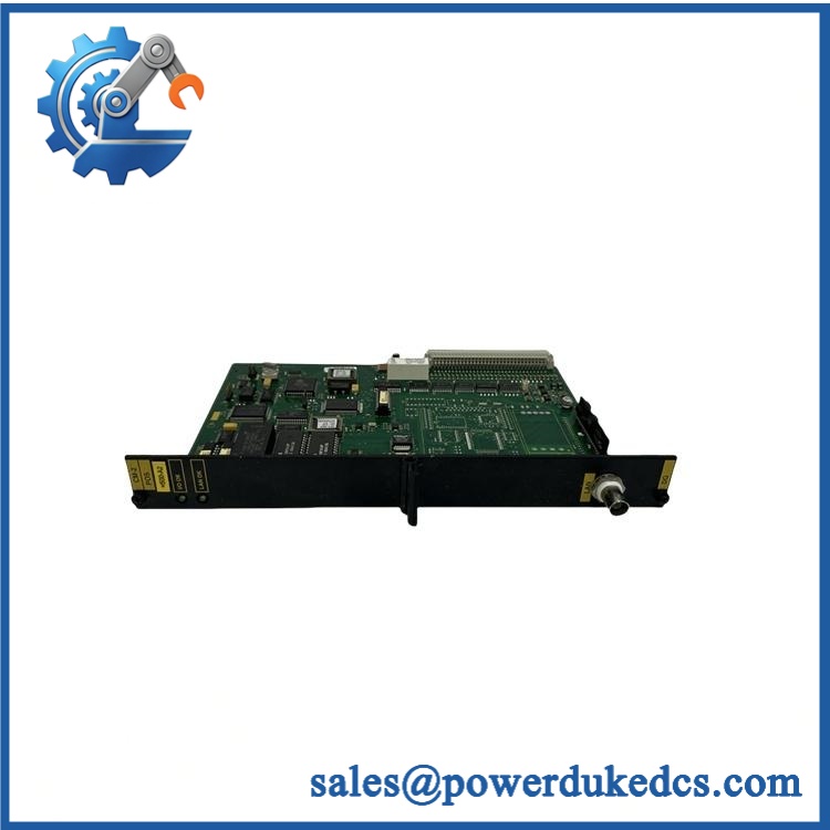
DEIF CM-2
Module 5: Migration, Compatibility & Installation Traps
Replacement Matrix
Exact CM-2 with matching DELOMATIC configuration: Drop-in Replacement
When the replacement has the same communication variant, hardware revision, DGU configuration, application program, and backplane arrangement, CM-2 can normally be exchanged as a like-for-like controller replacement.
CM-2 with different communication option: Software Compatible / Configuration Verification Required
The communication hardware must match the installed DGU. Verify whether the existing controller uses RS-232, RS-422, RS-485, or another documented interface option before ordering.
Different DEIF controller generation: Hardware Modification Required
A newer DELOMATIC controller should not be treated as a direct replacement for CM-2 without confirming rack, software, application, communication, and I/O compatibility.
⚠️ Field Traps (Watch Out)
Communication-variant trap: CM-2 configurations can differ by communication interface. Match the actual communication hardware and external wiring before installation.
Application-memory trap: CM-2 executes the DGU application program stored in its memory. A replacement that powers up correctly is not necessarily ready for service until the correct application configuration has been verified.
Address-setting trap: ARC-net and serial communication settings must match the existing system. Record node addresses, communication parameters, and switch settings before removing the original module.
Power-source trap: CM-2 receives its operating supply through the DELOMATIC power-supply module and backplane. Do not apply an external voltage directly to the controller unless the approved service procedure explicitly requires it.
Module 6: Quality Assurance SOP
Pre-Shipment QA Protocol for DEIF CM-2
- Step 1 — Identity Verification: Confirm DEIF marking, CM-2 model, communication variant, serial number, hardware revision, and associated DGU identification.
- Step 2 — OEM Anti-Counterfeit Visual Inspection: Inspect DEIF labels, PCB markings where accessible, communication interface hardware, connectors, DIP or address switches, mounting hardware, and evidence of unauthorized repair.
- Step 3 — Mechanical Inspection: Check the 6 TE housing, backplane connector, front and rear interfaces, PCB surface, locking arrangement, and connector contacts for cracks, corrosion, contamination, or deformation.
- Step 4 — Communication Variant Verification: Identify whether the unit is configured for RS-232, RS-422, RS-485, or another documented option. Record the exact hardware configuration.
- Step 5 — Power-On Self-Test: Install CM-2 in a compatible DELOMATIC rack and verify startup, module recognition, operating indication, and diagnostic status.
- Step 6 — Backplane Communication Test: Confirm correct communication between CM-2 and the installed DELOMATIC modules through the internal bus.
- Step 7 — ARC-Net Verification: Verify ARC-net communication, node addressing, and data exchange using an approved DEIF test configuration.
- Step 8 — Serial Interface Test: For RS-232, RS-422, or RS-485 variants, perform controlled transmit/receive testing with the applicable interface equipment.
- Step 9 — Application and Control Test: Verify the correct DGU application configuration and run representative generator-control functions under controlled test conditions.
- Step 10 — Final QC Record: Record model, communication variant, serial number, hardware revision, backplane result, ARC-net result, serial-interface result, application test result, visual condition, test date, and final QC disposition.
Technical Verification Note: DEIF CM-2 is the main controller used in the DELOMATIC 3 DGU architecture. It executes the application program and communicates with the other system modules through the backplane and ARC-net. The documented physical format is approximately 30.5 mm / 6 TE, with approximately 0.47 kg weight and 1.5 W typical / 3 W maximum power consumption. Communication configurations include RS-232, RS-422, and RS-485 options, while operating temperature is specified from approximately -25°C to +70°C.
Configuration Control Note: For spare-parts procurement, record the complete CM-2 hardware configuration rather than ordering only the generic model name. Communication interface type, hardware revision, DGU application version, address settings, and rack configuration can materially affect replacement compatibility.











 Start Chat


