

Description
- DEIF EPQ96-2 | Original Generator Automation Component
2. At-A-Glance Executive Brief
- Model: DEIF EPQ96-2
- Brand: DEIF
- Series: Uni-line / Electronic Potentiometer
- Part Type: Electronic Potentiometer / Governor Control Interface
- Core Function: Converts relay outputs from PI controllers, synchronizers, or load-sharing equipment into analog voltage/current or PWM signals for electronic speed governors.
- Primary Use: Generator control panels, marine propulsion systems, power management systems, and engine speed regulation applications.
- Key Specifications:
- Q96 panel mounting format
- 12–24 VDC supply range
- Analog output: ±10 VDC or ±20 mA
- PWM output: 0–6 VDC, 500 Hz
- Manual and automatic operating modes
- J1939 CAN input conversion capability
- Typical Deployment: Marine switchboards, genset control cabinets, and industrial engine governor systems.
3. Product Introduction
A generator speed-control loop can become unstable when the electronic governor expects a signal type that the existing PI controller cannot provide. The DEIF EPQ96-2 addresses this interface gap by acting as an electronic potentiometer replacement, converting relay step commands into proportional control signals for electronic governors or AVR-related applications. (This is especially relevant in retrofit projects where older synchronization equipment remains in service.)
Installed in a Q96 panel cutout, the EPQ96-2 provides manual and automatic adjustment functions without mechanical potentiometer wear. In field deployments, engineers commonly use this unit during generator upgrades, shipboard control repairs, and legacy automation replacements. Verify governor signal requirements before commissioning because output scaling, PWM settings, and ramp time parameters must match the receiving device.
4. Core Technical Specifications
| Parameter | Value |
|---|---|
| Manufacturer | DEIF |
| Model Number | EPQ96-2 |
| Product Type | Electronic Potentiometer |
| Application | Speed Governor / AVR Control Interface |
| Mounting Style | Q96 Panel Mount |
| Front Dimensions | 96 × 96 mm |
| Panel Cutout | 92 × 92 mm |
| Supply Voltage | 9–31.2 VDC (nominal 12/24 VDC) |
| Current Consumption | Approx. 10 mA at 24 VDC |
| Analog Voltage Output | 0…±10 VDC |
| Analog Current Output | 0…±20 mA |
| Output Load | Maximum 500 Ω |
| PWM Output | 0–6 VDC, 500 Hz ±50 Hz |
| CAN Interface | J1939 compatible input conversion |
| Resolution | 10-bit control resolution |
| Response Time | <0.1 s |
| Integrating Time | 2.5–25 s or 12.5–125 s |
| Accuracy | ±0.5% typical |
| Operating Temperature | -25°C to +70°C |
| Protection Rating | IP52 front / IP20 rear |
| Material | Self-extinguishing polycarbonate enclosure |
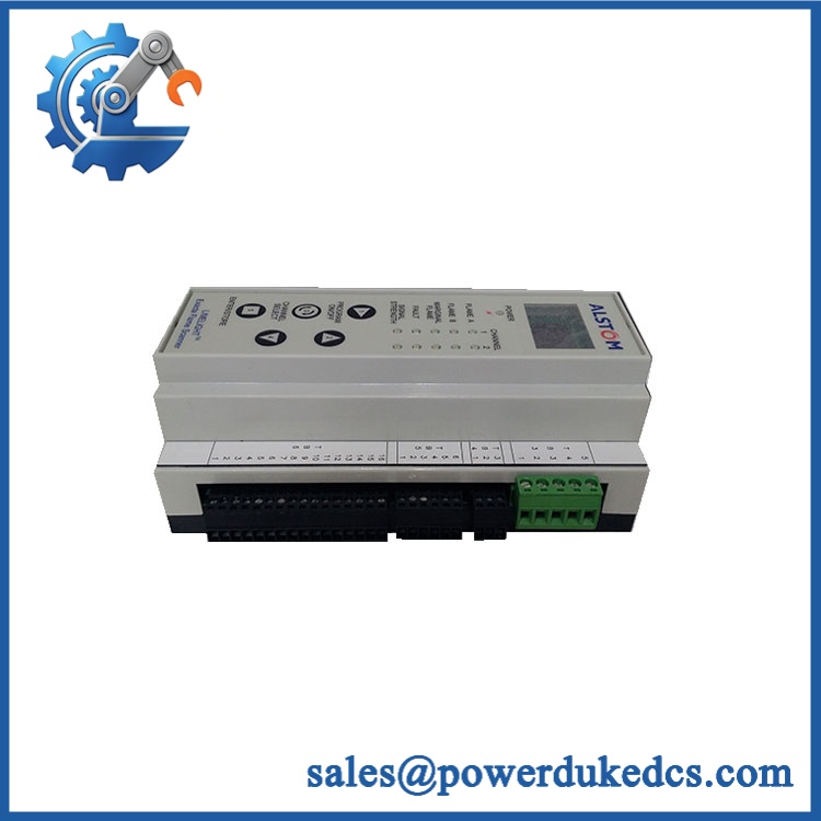
DEIF EPQ96-2
5. Application Scenarios & Pain Points
A speed governor interface failure can prevent a generator from synchronizing correctly even when the engine and control system remain operational.
- Marine generator control panels: The EPQ96-2 converts control signals for electronic governors on vessels where stable load response is required during changing operating conditions.
- Power generation systems: Used between PI controllers and governor inputs when legacy relay-based control equipment must interface with modern electronic speed systems.
- Engine retrofit projects: During modernization, this module helps maintain existing synchronization hardware while adapting output signals to newer governors.
- Offshore platforms: Installed in generator switchboards exposed to vibration and temperature variations above 50°C cabinet conditions.
- Industrial genset applications: Supports manual/automatic speed adjustment where operators require direct control during commissioning or maintenance.
6. Common Error Codes & Diagnostic Symptoms
Symptom/Code: Governor Does Not Respond to Increase/Decrease Commands
→ Diagnosis: Possible incorrect output wiring, failed analog conversion circuit, or incorrect manual/auto mode setting.
→ Action: Verify terminal connections and replace the EPQ96-2 if output signals remain unavailable.
Symptom/Code: Speed Signal Oscillation / Unstable Frequency Adjustment
→ Diagnosis: Incorrect ramp time setting, output scaling mismatch, or unstable input command from the PI controller.
→ Action: Adjust parameters and verify governor input requirements.
Symptom/Code: No PWM Output Signal
→ Diagnosis: PWM configuration error, internal output stage fault, or incorrect rear adjustment settings.
→ Action: Check PWM parameters and replace the module if output hardware fails.
7. Cross-Reference & Lifecycle Migration
- Related DEIF Products:
- EPQ96 electronic potentiometer family
- EPN-110DN DIN rail electronic potentiometer
- DEIF generator control products using analog/PWM interfaces
- Replacement Considerations:
- Confirm output signal type required by the governor.
- Verify panel dimensions and terminal wiring.
- Check whether CAN/J1939 functionality is required.
- Firmware Requirements:
The EPQ96-2 is primarily hardware-parameter configured. Replacement normally requires adjustment of settings rather than PLC-style firmware loading. - Lifecycle Status: Active / Mature Product
- Still supported within generator and marine automation applications.
- Maintain calibrated spare units for critical generator control panels.
- Stock Strategy:
Keep tested replacement units available where generator synchronization or speed control availability is important.
8. Field Engineer’s Tech Notes (Anti-Pitfall Guide)
- Do not assume the governor accepts the same signal type as the old potentiometer.
A common mistake during retrofit work is replacing a mechanical potentiometer with an electronic unit without confirming whether the governor expects voltage, current, or PWM input. - Check the terminal wiring before adjusting parameters.
The EPQ96-2 supports multiple output methods, and incorrect terminal connections can appear as a configuration problem (when the actual issue is wiring).
9. Strict QA & Testing SOP
Step 1 — Incoming Inspection
- Confirm DEIF EPQ96-2 model marking.
- Record serial number and manufacturing information.
- Inspect front display, buttons, housing, and terminals.
- Photograph physical condition.
Step 2 — Electrical Testing
- Apply controlled 12/24 VDC supply.
- Verify startup behavior.
- Measure current consumption.
- Check output voltage/current generation.
Step 3 — Signal Interface Testing
- Test analog output range from minimum to maximum.
- Verify PWM frequency and duty-cycle response.
- Confirm manual/automatic mode switching.
Step 4 — Communication Testing
- Verify J1939 interface where applicable.
- Confirm CAN signal conversion operation.
Step 5 — Packaging Control
- Place tested unit in protective packaging.
- Protect front panel and terminal connectors.
- Use moisture protection for international shipment.
Test videos are available for verified inspection records.
10. Buyer’s FAQ (Dynamic Q&A)
Q: Can the DEIF EPQ96-2 be hot-swapped during generator operation?
A: It is not recommended unless the specific switchboard design allows live replacement. Removing a speed-control interface during operation may affect generator control response.
Q: How do I confirm this is a New Original DEIF EPQ96-2?
A: Check the DEIF label, model number, housing condition, terminal quality, and supplier inspection records. Original units should have traceable product identification.
Q: Does the EPQ96-2 require programming after replacement?
A: It normally requires parameter adjustment rather than application programming. Verify output range, ramp time, preset values, and operating mode settings before commissioning.
Q: What warranty information should be confirmed before purchase?
A: Confirm warranty duration, functional test coverage, replacement conditions, and whether inspection records are supplied. For generator control components, verified testing documentation reduces commissioning risk.



 Start Chat


