Description
-
Brand: DEIF
-
Full Model Number: IOM4.2
-
Lifecycle Status: Legacy module; the associated DM-4 Gas platform has been phased out by DEIF
-
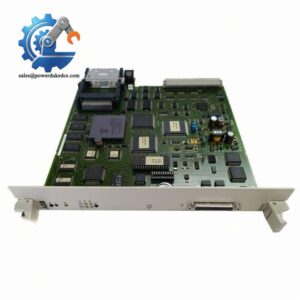
Core Function: 40-channel multifunction input/output module for the Delomatic 400 gas and hydro control system
-
Top 3 Technical Specs: 12 digital inputs, 4 frequency/digital inputs, and 10 digital outputs; 6 temperature inputs supporting Pt100, Pt1000, or NiCr-Ni sensors; 4 analog inputs and 4 analog outputs
-
Analog Input Specifications: -20 to +20 mA or -10 to +10 V; 16-bit resolution in the published Delomatic 400 Gas specification
-
Analog Output Specifications: -20 to +20 mA; 0–500 Ω load; 12-bit resolution
-
Digital I/O Specifications: 9–36 VDC signal ranges for the documented digital channels; digital outputs rated for 0–200 mA source or sink per channel
-
Electrical Isolation: Optical insulation from other potentials, specified at 550 VAC in the applicable datasheet
-
Module Size: 6TE; 30.48 mm nominal rack width
-
Stock & Condition: Physical stock, new-surplus or used condition, hardware revision, functional test evidence, and dispatch lead time require confirmation
Obsolescence & Supply Chain Deep Dive
When a legacy generator-control system develops an I/O fault, locating the exact replacement can become a critical maintenance issue. The DEIF IOM4.2 is a multifunction I/O module designed for the Delomatic 400 control platform, including gas-engine and hydro-turbine applications. Its 40-channel arrangement combines temperature measurement, analog signal processing, digital inputs, frequency measurement, and digital outputs in one rack-mounted assembly. DEIF has phased out its DM-4 Gas platform and does not currently list a direct replacement for that system. Consequently, matching the original module and documenting its operating condition are important steps when restoring an installed system.
Replacing a failed IOM4.2 may cost less than migrating the entire control architecture, particularly when the existing rack, application software, sensors, and field wiring remain serviceable. The TCO comparison should include the replacement module, freight, technician labor, functional testing, and expected downtime. A broader migration introduces additional costs for controller hardware, I/O redesign, signal remapping, application engineering, commissioning, and shutdown planning. A verified legacy spare can therefore support continued operation without requiring an immediate system-wide upgrade. However, the replacement decision should account for the remaining availability of compatible modules and the longer-term cost of maintaining the phased-out platform.
Compatibility & Replacement Matrix
|
Evaluation Item |
Engineering and Procurement Guidance |
|---|---|
|
Replacement classification |
Conditional drop-in replacement for a matching IOM4.2 configuration in a compatible Delomatic 400 rack |
|
Hardware compatibility |
Verify the complete module identification, hardware revision, rack arrangement, connectors, and backplane interface |
|
Software compatibility |
Confirm the installed PCM controller, application software, I/O assignment list, and channel configuration |
|
Firmware requirements |
Do not assume a firmware flash is necessary or supported. Establish the required software and hardware combination before installation |
|
Hardware modification |
Normally not expected for a verified like-for-like replacement; wiring or configuration changes may be necessary if the original setup differs |
|
Analog input compatibility |
Verify current or voltage input selection, signed measurement range, channel mapping, and scaling |
|
Temperature input compatibility |
Confirm Pt100, Pt1000, or NiCr-Ni sensor type and the required 2-, 3-, or 4-wire arrangement for resistance temperature sensors |
|
Digital output compatibility |
Confirm the external 9–36 VDC supply, output load, source/sink configuration, and protection requirements |
|
Estimated replacement time |
Approximately 2–4 technician-hours for a like-for-like exchange and basic channel checks, excluding extended commissioning or fault diagnosis |
|
Cost estimate |
Budget 2–4 technician-hours at the site’s labor rate, plus the quoted module price, freight, and any additional engineering or shutdown costs |
|
Acceptance requirement |
Verify input readings, output behavior, temperature measurement, frequency acquisition, and controller diagnostics before returning the system to service |
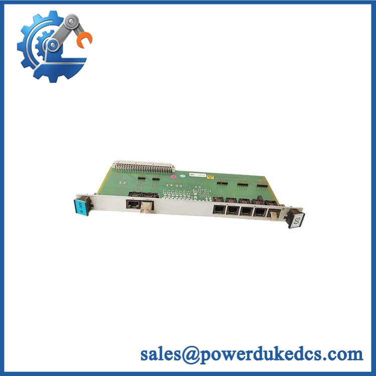
DEIF IOM4.2
Field Traps to Check Before Ordering
Hardware revision and application configuration
An IOM4.2 designation alone does not establish that every revision is interchangeable in every Delomatic 400 installation. Confirm the original module markings and compare the proposed replacement against the applicable installation documentation. Before removal, preserve the existing I/O assignment records and controller configuration. After installation, verify that each signal is associated with the intended channel and control function.
Signal-range and wiring mismatch
The module supports several signal types, so incorrect field wiring can produce misleading readings or damage equipment. Analog inputs support -20 to +20 mA or -10 to +10 V in the documented Delomatic 400 Gas configuration. Temperature measurement requires the correct sensor type and wiring arrangement. Digital outputs need a compatible external supply and must remain within their specified load limits. Check terminal assignments, grounding, isolation requirements, and configured signal ranges before energizing the system.
Quality Assurance & Testing SOP
For this legacy module, the inspection process should establish both physical condition and demonstrated I/O performance. Testing must use a compatible Delomatic 400 rack or an appropriate test fixture, with the applicable hardware revision and technical specifications available to the QA technician.
|
QA Stage |
Required Action |
Acceptance Evidence |
|---|---|---|
|
Identification and traceability |
Record DEIF branding, IOM4.2 identification, available serial or lot information, and PCB revision markings |
Photographs and completed inspection record |
|
OEM anti-counterfeit visual inspection |
Examine labels, PCB markings, connectors, component placement, solder joints, and signs of unauthorized repair |
Documented observations and investigation of discrepancies |
|
Physical condition inspection |
Inspect the terminal blocks, board edges, mounting points, and components for corrosion, cracks, contamination, or damage |
Condition report and inspection photographs |
|
Rack installation check |
Install the module in a compatible test rack following the approved isolation and handling procedure |
Mechanical fit, connector engagement, and startup observations |
|
Power-on self-test |
Energize the compatible rack and review PCM diagnostics, startup status, and module fault indications |
Recorded startup results and diagnostic findings; check ERR/RUN indicators only where fitted and specified |
|
Digital input testing |
Apply controlled input signals within the documented 9–36 VDC operating range and verify the corresponding channel states |
Input-by-input test results |
|
Frequency input testing |
Apply reference pulses at representative frequencies within the supported 0–20 kHz range |
Measured frequency results and channel response |
|
Temperature input testing |
Use suitable resistance simulators or thermocouple equipment for the configured sensor type |
Recorded readings at selected test points, evaluated against applicable accuracy limits |
|
Analog input testing |
Apply calibrated current and voltage signals at representative points across the configured range |
Recorded signal values, controller readings, and deviation from expected results |
|
Analog output testing |
Command representative output values and measure current with a suitable reference instrument; verify the load remains within specification |
Output readings and load-test records |
|
Digital output load testing |
Exercise each output using an approved load within the specified operating limits, checking switching behavior and fault protection where practical |
Channel response, measured output, and documented load conditions |
|
Isolation and channel checks |
Verify applicable electrical isolation requirements and check for unintended interactions between signal groups |
Test results against the relevant acceptance criteria |
|
Final inspection and packing |
Reinspect connectors and terminals, record completed tests, and protect the module against electrostatic discharge and mechanical damage |
Final QA report and packing confirmation |
QA release criteria: A visual inspection or successful power-on check does not establish full functional compliance. Where a suitable test rack or calibrated signal equipment is unavailable, identify the untested functions before shipment. Record actual results rather than describing the unit as fully tested based solely on external appearance.
Procurement & Lifecycle FAQ
Is the DEIF .2 genuinely in stock, and what is the cutoff for emergency shipping?
Physical availability must be confirmed against the actual allocated unit. For urgent maintenance orders, request current stock confirmation, photographs of the identification label, the condition grade, available test records, and the earliest confirmed dispatch date. Same-day shipment depends on order approval, payment clearance, packaging, export documentation, and carrier collection times. No dispatch commitment should be assumed without written confirmation.
How do you verify the authenticity and condition of a discontinued .2?
Request photographs of the actual module, its identification markings, PCB revision, connectors, and terminal sections. Ask whether the unit is new surplus, used, or tested refurbished, and obtain the inspection results available for that specific unit. Where traceability is required, request supporting documentation. Visual inspection alone cannot establish authenticity, and a power-on test alone cannot demonstrate that all 40 channels function correctly.
Are there firmware or software compatibility issues engineers should check before issuing the PO?
Yes. The installed PCM controller, application software, I/O assignment list, and module revision must be checked against the intended replacement. Confirm channel allocation and the configured signal ranges before installation. A firmware change should not be assumed necessary; nor should it be attempted without an approved procedure. Engineering approval should precede substitution of another I/O module type.
What warranty and return terms apply to the DEIF .2?
The supplier’s quotation or pro forma invoice should specify the warranty period, covered defects, dead-on-arrival reporting window, and return authorization procedure. For surplus or used stock, clarify whether coverage includes functional failures discovered during commissioning and whether the unit must pass agreed acceptance tests. Any exclusions for installation damage, incorrect wiring, or unauthorized modifications should be disclosed before the purchase order is released.
Can the DEIF .2 be replaced with a newer DEIF I/O module?
Not as an automatic drop-in replacement. The .2 belongs to the legacy Delomatic 400 architecture, whereas newer DEIF I/O modules may use different rack interfaces, communication protocols, software configuration, and signal assignments. A migration requires engineering assessment of channel requirements, controller compatibility, field wiring, application logic, and commissioning scope. For an urgent restoration, a verified matching .2 is the more direct option; for a planned modernization, compare the full migration cost against the expected remaining service life of the existing system.