

Description
- DEIF PPU/2/GS | Factory Tested Power Management Spare
2. At-A-Glance Executive Brief
- Model: DEIF PPU/2/GS
- Brand: DEIF
- Series: Multi-Line 2 (ML-2) Generator Control Platform
- Part Type: Generator Paralleling & Protection Unit
- Core Function: Controls generator synchronization, load sharing, protection functions, and power management operations in standalone or parallel generator systems.
- Key Specs:
- Three-phase true RMS measurement system.
- Galvanically isolated voltage and current inputs.
- Supports generator parallel operation with mains or other generator sets.
- 12/24 VDC supply system.
- Reverse power, overcurrent, and generator protection functions.
- Suitable for marine and industrial power applications.
3. Product Introduction
Structure C — Data-Driven
Three-phase measurement, 12/24 VDC operation, and generator paralleling control define the role of the DEIF PPU/2/GS in power management systems. This Multi-Line 2 controller combines protection functions, synchronization control, and load-sharing capability inside a dedicated generator automation unit.
Within shipboard and industrial generator installations, the PPU/2/GS manages critical electrical operations between generator sets, switchgear, and external control equipment (—which is essential when multiple power sources must remain stable during changing loads). Before replacement, verify application parameters, relay configuration, communication options, and protection settings. The hardware replacement alone does not restore the original generator control strategy without proper commissioning.
4. Core Technical Specifications
| Parameter | Value |
|---|---|
| Manufacturer | DEIF |
| Model | PPU/2/GS |
| Product Type | Generator Paralleling & Protection Unit |
| Product Family | Multi-Line 2 |
| Application | Generator control, protection, synchronization |
| Supply Voltage | 12/24 VDC |
| Measuring Voltage | 100–690 VAC |
| Measuring Current | -/1 A or -/5 A CT input |
| Measurement System | Three-phase true RMS |
| Voltage / Current Inputs | Galvanically isolated |
| Relay Outputs | Configurable protection/control outputs |
| Analog Outputs | 0–20 mA / ±20 mA depending on option |
| Communication | RS-232 / optional communication interfaces |
| Control Functions | Synchronizing, load sharing, fixed power, droop control |
| Protection Functions | Reverse power ANSI 32, overcurrent ANSI 51 |
| Mounting | DIN rail or base mounting |
| Operating Temperature | -25°C to +70°C |
| Storage Temperature | -40°C to +70°C |
| Environmental Rating | Marine industrial environment |
| Approximate Weight | Main unit approx. 1.5 kg |
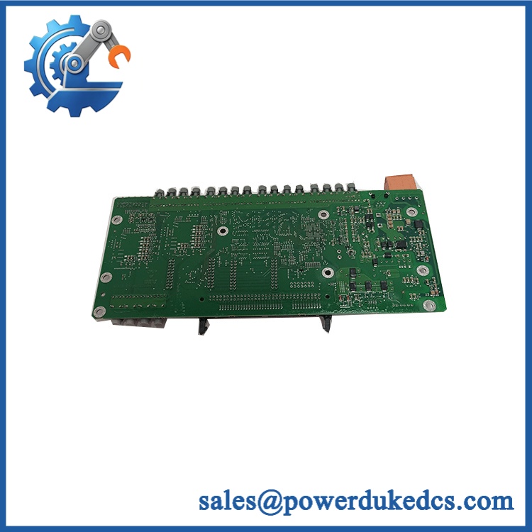
DEIF PPU/2/GS
5. Application Scenarios & Pain Points
Micro-case study approach:
A vessel operating with two diesel generator sets experiences unstable load distribution after a controller failure. The generators remain mechanically available, but incorrect synchronization and load-sharing behavior prevent normal operation. Replacing the DEIF PPU/2/GS and restoring approved parameters returns the power management system to normal service.
- Marine Power Systems: Used on vessels requiring automatic generator synchronization and stable load distribution.
- Offshore Platforms: Supports distributed generator operation where electrical availability is critical.
- Industrial Backup Power: Controls generator sets operating in standby or parallel modes.
- Power Plants: Applied in auxiliary generation systems requiring protection coordination.
- Retrofit Projects: Maintains existing Multi-Line 2 installations during lifecycle extension programs.
In engine rooms where cabinet temperatures exceed 50°C, inspect ventilation paths, terminal tightening, and power supply stability before installing replacement controllers.
6. Common Error Codes & Diagnostic Symptoms
Symptom/Code: Generator Fail to Synchronize
→ Diagnosis: Incorrect voltage/frequency matching, damaged measurement inputs, or configuration mismatch may prevent synchronization.
→ Action: Verify sensing circuits and controller parameters, then replace the PPU/2/GS if hardware failure is confirmed.
Symptom/Code: Reverse Power Trip / ANSI 32 Alarm
→ Diagnosis: Incorrect generator load measurement, CT wiring problems, or faulty measurement channels may trigger protection action.
→ Action: Check CT polarity and measurement wiring before replacing the controller.
Symptom/Code: Load Sharing Instability
→ Diagnosis: Communication failure, incorrect droop settings, or analog control output faults may affect generator balancing.
→ Action: Verify settings and replace the unit if output hardware failure exists.
7. Cross-Reference & Lifecycle Migration
- Platform Compatibility: DEIF Multi-Line 2 generator control systems.
- Related Product Family: PPU-2 generator paralleling and protection unit.
- Replacement Consideration: The PPU/2/GS has been replaced in DEIF’s product program by newer PPU 300 solutions.
- Firmware Requirement: Configuration migration may be required when moving between generations.
- Parameter Transfer: Generator ratings, protection limits, synchronization settings, and load-sharing parameters must be documented before replacement.
- Lifecycle Status: End of Life / Legacy Support
For spare inventory management, maintain verified PPU/2/GS units with recorded firmware revision and configuration backup. A controller without the original parameter set can create extended commissioning time.
8. Field Engineer’s Tech Notes (Anti-Pitfall Guide)
- Never replace the controller without saving the parameter file first.
Generator protection settings are application-specific. Missing reverse power limits, synchronization windows, or load-sharing values can cause commissioning problems. - Inspect CT wiring before replacing the hardware.
Incorrect current transformer polarity often appears as a controller failure. Confirm phase sequence and measurement polarity before removing the unit.
9. Strict QA & Testing SOP
A professional inspection process for DEIF PPU/2/GS should include:
Step 1 — Incoming Inspection
- Verify model marking: PPU/2/GS.
- Record serial number and hardware revision.
- Inspect enclosure, terminals, display interface, and mounting points.
- Photograph external condition.
Step 2 — Electrical Verification
- Confirm 12/24 VDC supply operation.
- Check measurement input response.
- Verify relay output condition.
Step 3 — Functional Testing
- Connect to a compatible generator control test system.
- Verify synchronization logic.
- Test protection monitoring.
- Confirm load-sharing functions.
Step 4 — Configuration Review
- Compare parameter backup.
- Record firmware revision.
- Verify communication settings.
Step 5 — Packaging Control
- Place controller in anti-static protective packaging.
- Add shock protection for transport.
- Include inspection records.
Test videos, electrical verification records, and inspection photographs are available for quality review.
10. Buyer’s FAQ (Dynamic Q&A)
Q1. Can the DEIF PPU/2/GS be hot-swapped during generator operation?
A: No. Generator protection controllers should normally be replaced only after following approved shutdown and isolation procedures. Removing an active protection unit can affect generator safety functions.
Q2. “How do I confirm this is a genuine DEIF PPU/2/GS?”
A: Verify the DEIF nameplate, serial number, hardware revision, terminal configuration, and supplier inspection records. Legacy power controllers require traceable identification.
Q3. Does the PPU/2/GS include the latest firmware and generator settings?
A: Hardware availability does not guarantee application configuration. Generator parameters, protection thresholds, and communication settings usually require restoration from the original backup.
Q4. What warranty information should be requested for this discontinued controller?
A: Request written warranty terms, functional test results, and condition classification. For legacy DEIF equipment, documented testing is important



 Start Chat


