

Description
- Brand DEIF
- Full Model Number PSM-1
- System/Series Family DEIF Delomatic-3 / DGU
- Core Function Internal power supply module providing power to the other Delomatic modules within a DGU
- Top 3 Hardcore Specs 1 PSM-1 required per DGU | Delomatic-3 internal power distribution | Dedicated DGU power-supply module
- Stock Status New Surplus — verify exact part number, hardware revision, input supply version, and DGU compatibility before shipment
Module 3: Technical Product Introduction
When a Delomatic generator control unit loses its internal module supply, multiple control and I/O functions can disappear simultaneously. The DEIF PSM-1 is the dedicated Power Supply Module for the Delomatic-3 system. DEIF’s official Delomatic-3 documentation identifies PSM-1 as the power-supply module for the other modules installed in the DGU, and the system architecture requires one PSM-1 for each DGU. DEIF also notes that certain safety functions require an independent external supply rather than relying on the PSM-1 alone.
The critical procurement point is that is a system-specific module, not a generic DIN-rail power supply. Public listings associate with Delomatic-3 and, for a commonly listed assembly number 1044220060F, describe a 24 VDC nominal input and regulated 24 VDC output. Other secondary sources publish substantially different electrical data, including wide-range AC/DC input values, so those figures should not be generalized to every revision. The exact module label and DEIF documentation for the installed DGU should control the final electrical specification.
Module 4: Application Scenarios & Field Realities
- Inside a Delomatic-3 DGU, the supplies the other control-system modules installed in the generator unit. A fault can therefore produce several secondary symptoms at once, including apparent CM-2, IPM-1, OPM-1, or SCM-1 failures.
- During a generator-control startup failure, check the power path before replacing the control module. A common supply problem can make an otherwise healthy DGU appear completely inactive.
- On marine and offshore generator installations, the operates as part of the Delomatic modular architecture. DEIF’s current documentation provides dedicated documentation and a specific replacement instruction for the module, confirming that it is a defined service component within Delomatic-3.
- During planned DGU maintenance, one is allocated to each DGU. The replacement procedure should therefore verify not only the module itself but also the downstream power distribution to CM-2, SCM, IPM, OPM, and other installed modules.
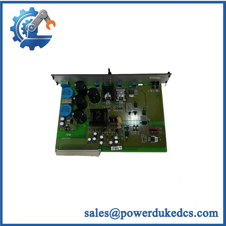
DEIF PSM-1
Module 5: Migration, Compatibility & Installation Traps
Replacement Matrix
| Replacement Status | Engineering Assessment |
|---|---|
| Drop-in Replacement | Yes, for an exact replacement in the same Delomatic-3 DGU configuration with matching hardware revision and supply arrangement. |
| Software Compatible | Not normally applicable to the power-conversion function. The is not the application controller, although the complete DGU must initialize correctly after replacement. |
| Hardware Modification Required | Normally no for an exact replacement. Modification may be required when changing revisions, input-supply variants, rack architecture, or DGU generations. |
⚠️ Field Traps: Watch Out
Do not use a generic 24 VDC power supply as an automatic substitute. The is part of the Delomatic-3 modular architecture and its mechanical interface, internal distribution, monitoring, and connector arrangement are system-specific.
Verify the exact part number behind “.” Current secondary references associate 1044220060F with , while the official DEIF documentation identifies by functional module name rather than establishing that every unit shares one universal electrical configuration. Record the complete physical label before procurement.
Check the downstream module power path. Replacing the does not prove that the CM-2, SCM, IPM, OPM, or other modules are receiving correct voltage. After installation, verify each downstream supply path under actual DGU loading.
Do not assume safety circuits are powered exclusively by . DEIF explicitly notes that some safety functions require an external independent power supply. A DGU that remains partially inactive after a replacement may therefore have a separate supply-path issue.
Inspect the module before energization. Check connector condition, mounting engagement, terminal integrity, and evidence of overheating. A replacement with a sound output voltage can still fail because of a damaged backplane or poor connection.
Module 6: Quality Assurance SOP
A surplus should be tested as a complete Delomatic-3 power module, with emphasis on supply stability and downstream module operation.
- OEM anti-counterfeit visual inspection: Verify DEIF identification, exact designation, assembly number, revision marking, connector arrangement, enclosure, and manufacturing identifiers against controlled DEIF references.
- Part-number and traceability check: Record the complete part number, hardware revision, serial number, date code, and any DGU or project identification.
- Mechanical inspection: Examine connectors, card guides, mounting hardware, PCB surfaces, terminals, and enclosure condition for bent contacts, corrosion, contamination, cracking, discoloration, or unauthorized repair.
- Power-input identification: Determine the correct input supply from the exact revision and equipment documentation before applying laboratory power. Do not use an assumed universal input range.
- Power-on self-test (POST): Install the in an approved Delomatic-3 test arrangement and verify expected startup and module-status behavior.
- Input-supply verification: Apply a controlled source matching the confirmed specification and monitor voltage stability, startup current, and abnormal heating.
- Output-rail verification: Measure every documented output rail under no-load and representative-load conditions, comparing the result with the controlled DEIF specification for the tested revision.
- Load regulation test: Apply controlled electronic loads representative of the downstream Delomatic modules and verify output-voltage stability during load changes.
- Current-capacity verification: Test the power output under controlled loading without exceeding the documented module limits.
- Protection test: Where the approved fixture permits, verify short-circuit, over-current, and thermal protection behavior using current-limited test equipment.
- Ripple and noise test: Measure output ripple and high-frequency noise under representative load conditions to identify abnormal switching or filter performance.
- Downstream distribution test: Connect representative CM-2, SCM-1/SCM-2, IPM-1, and OPM-1 loads and confirm that the maintains the required supply under combined operating conditions.
- Module-startup sequence test: Verify that downstream Delomatic modules initialize correctly after power application and that no unexpected supply-related diagnostic condition is generated.
- Supply-loss recovery test: Apply a controlled input interruption according to the approved maintenance procedure and verify expected recovery and downstream module restart behavior.
- Temperature inspection: Monitor power-conversion components and connectors during extended loading, looking for abnormal temperature rise or unstable output behavior.
- System recognition test: Confirm that the Delomatic-3 DGU initializes correctly with the tested installed and that all expected powered modules become available.
- Communication handshake verification: The is a power-supply module rather than a primary communications processor. Verify communication by checking the complete DGU after power is restored, including CM-2 and the applicable SCM/IPM/OPM modules.
- Fault-diagnostic test: Introduce only approved, current-limited supply faults and verify the expected power or DGU diagnostic response.
- Extended-run test: Operate a representative Delomatic-3 DGU load continuously while monitoring output voltage, current, ripple, temperature, downstream module status, and intermittent resets.
- Final QC record: Document exact part number, revision, verified input configuration, output-rail measurements, load test, protection response, ripple, downstream module startup, extended-run results, traceability, and packaging condition.
Technical Identification Note: DEIF’s official Delomatic-3 documentation identifies as the Power Supply Module for the other modules installed in each DGU, with one required per DGU. DEIF also maintains a dedicated data sheet and replacement instruction. Secondary inventory references commonly associate 1044220060F with the assembly, but published electrical specifications vary between listings. The exact physical part number and revision should therefore be verified before treating any input/output voltage figures as confirmed specifications.











 Start Chat


