

Description
- Brand: ALSTOM
- Full Model Number: DSI1817 TRVC062335000 CP00003934
- System/Series Family: ALSTOM railway traction and converter control systems
- One-Sentence Core Function: Control interface board used for signal processing and communication within an ALSTOM traction-control architecture
- Top 3 Hardcore Specs: DSI1817 control/interface board; TRVC062335000 hardware reference; CP00003934 configuration identifier
- Stock Status: Stock condition and exact hardware revision to be confirmed
Module 3: Technical Product Introduction
A failed interface board can interrupt the signal path between traction-control electronics, converter equipment, and vehicle-level control systems without making the upstream controller appear defective. ALSTOM DSI1817 TRVC062335000 CP00003934 is identified in available industrial references as an ALSTOM control/interface board associated with railway traction and converter equipment. The DSI1817 reference is also described by secondary sources as a digital signal interface module used within distributed ALSTOM control architectures.
The complete identification is particularly important for this product. DSI1817 identifies the board family, TRVC062335000 identifies the ALSTOM hardware reference, and CP00003934 identifies the configuration or procurement reference. Publicly available documentation for this exact combination is limited, and conflicting secondary sources assign different I/O and processor specifications. For that reason, fixed values for CPU type, memory capacity, channel count, communication protocol, supply voltage, and environmental rating should be confirmed from the physical nameplate and vehicle-specific ALSTOM documentation before being treated as certified specifications.
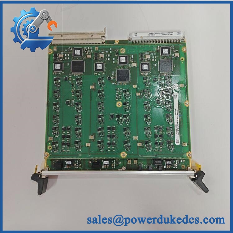
ALSTOM DSI1817 TRVC062335000 CP00003934
Module 4: Application Scenarios & Field Realities
- Within traction-converter control cabinets, the DSI1817 can form part of the interface chain between power-conversion electronics and higher-level vehicle control. When a converter channel stops responding, inspect the board’s supply, connector seating, communication path, and associated gate or feedback circuitry before replacing the interface board.
- For metro, locomotive, or electric multiple-unit equipment, the exact CP00003934 configuration should be preserved. Railway control electronics are frequently tailored to a particular vehicle platform, converter package, or software baseline, so a board from another configuration should not be assumed interchangeable simply because the main board number matches.
- During converter maintenance, connector integrity is a practical failure point. Repeated thermal cycling and vehicle vibration can contribute to contact fretting or connection resistance; inspect the mating connector and retention hardware together with the PCB.
- When troubleshooting intermittent traction-control faults, capture diagnostic information before swapping hardware. A communication timeout, missing feedback value, or converter protection event may originate in wiring, power supply, sensor circuitry, or the vehicle control network rather than in the itself.
Module 5: Migration, Compatibility & Installation Traps
Replacement Matrix
Replacement Classification: Configuration-Matched Replacement — Exact Vehicle and Hardware Revision Required
A like-for-like TRVC062335000 CP00003934 replacement should be treated as a direct hardware exchange only when the vehicle configuration, rack position, connector arrangement, hardware revision, and associated software baseline match the original installation.
→ Different configuration: Configuration Verification Required. Similar hardware can carry different vehicle-specific configurations. The complete TRVC062335000 / CP00003934 identification should therefore remain attached to the purchasing record.
→ Generic traction-control interface board: Hardware Modification Required. A generic interface card cannot be assumed to reproduce the original signal processing, connector assignment, communication behavior, or vehicle-control configuration.
⚠️ Field Traps — Watch Out
1. Configuration-code mismatch: Do not procure this part using “” alone. The and identifiers are essential for distinguishing the requested configuration.
2. Unverified I/O definition: Public reseller sources give inconsistent descriptions of the , including different claims concerning digital I/O, analog inputs, and communication interfaces. Verify the exact board against the vehicle wiring diagram rather than relying on generic catalog descriptions.
3. Firmware and vehicle configuration: A physically matching replacement can still require the correct software or configuration baseline. Record the original firmware, parameter set, and vehicle-control configuration before replacement where the installed system permits this.
4. Railway vibration and connector condition: Mechanical seating matters. Inspect card guides, locking hardware, connector contacts, and PCB mounting points before concluding that an intermittent fault is electronic.
Module 6: Quality Assurance SOP
Each ALSTOM should undergo identification, electrical, interface, and system-level testing before shipment.
- OEM identification visual inspection: Verify ALSTOM markings, , , , serial number, hardware revision, PCB identification, and connector labels.
- Configuration capture: Photograph the complete nameplate and all revision markings. Record the entire material number rather than shortening the item to .
- Mechanical inspection: Examine the PCB, connector contacts, card guides, retention hardware, mounting points, components, and accessible solder joints for impact, contamination, corrosion, thermal damage, or previous repair.
- Connector inspection: Check every external and backplane connector for bent contacts, fretting, oxidation, looseness, or damaged locking hardware.
- Power verification: Apply only the supply specified for the exact board revision using an approved ALSTOM-compatible laboratory test arrangement. Do not rely on conflicting third-party voltage specifications.
- Power-on self-test (POST): Confirm normal initialization, diagnostic indicators, and board startup behavior.
- Processor and memory verification: Where diagnostic access is available, record detected processor, memory, firmware, and board-identification information and compare it with the customer’s baseline.
- Digital interface test: Exercise the applicable digital signal paths using an approved interface simulator and verify correct input/output state recognition.
- Analog interface test: Where the exact configuration includes analog channels, apply calibrated signals appropriate to the documented interface and verify correct conversion and scaling.
- Communication test: Verify the board’s applicable vehicle or rack communication interface using the approved ALSTOM test configuration. Do not assume a generic RS-485, Ethernet, or other interface without confirming the exact board revision.
- Signal-integrity test: Monitor representative control and feedback signals under static and dynamic test conditions and verify stable transfer without intermittent errors.
- Fault-response test: Simulate authorized communication, sensor, or interface faults and confirm the expected diagnostic response.
- Configuration verification: Compare firmware and configuration information with the vehicle-specific baseline before release.
- Thermal stability test: Operate the board under representative load while monitoring supply stability, communication errors, diagnostic status, and temperature.
- Extended functional test: Maintain representative I/O and communication activity for an extended period to detect intermittent resets, communication loss, or signal instability.
- Final QC record: Retain complete identification photographs, hardware revision, processor and firmware information, connector inspection results, communication tests, I/O results where applicable, fault-response observations, thermal data, and final QC approval.
The ALSTOM is best handled as a configuration-specific railway control/interface board associated with ALSTOM traction and converter control equipment. Available industrial references identify with this exact TRVC and CP reference, but the public technical data is inconsistent regarding detailed processor, I/O, and communications specifications.
For spare-parts control, preserve the complete identification. The critical compatibility checks are the vehicle platform, rack position, connector assignment, hardware revision, firmware/configuration baseline, power requirements, and actual installed signal interfaces. Do not release a replacement based on the family number alone.











 Start Chat


