

Description
- Model: GE 369
- Brand: GE / GE Multilin
- Series: Multilin 369 Motor Management Relay
- Part Type: Microprocessor-based motor protection, control, metering, and management relay
- Core Function: Protects and manages three-phase motors through thermal, current, voltage, ground-fault, mechanical, and control functions, depending on the ordered configuration.
- Key Specs: 1 A / 5 A CT inputs; configurable LO or HI control-power ranges; front RS-232 and rear RS-485 communications; Modbus RTU; optional RTD inputs and expanded communications. GE currently classifies the 369 as a Legacy product and states that manufacturing has been discontinued.
Product Introduction
In a motor control lineup, the GE Multilin 369 sits between field instrumentation and the plant protection/control system, processing current, voltage, temperature, and status information to make motor-protection decisions. It was designed for medium-voltage motor applications and combines protection, control, monitoring, metering, and communications in one relay.
The hardware accepts 1 A or 5 A CT secondary inputs, with current measurement ranges extending up to 20 × CT primary current. Control power depends on the ordered version: the documented LO range is 24–48 V AC/DC, while the HI version accepts 110–250 VDC or 100–240 VAC. That distinction is critical when replacing an installed unit (the front-panel model name alone does not establish the control-power variant).
Core Technical Specifications
| Parameter | Value |
|---|---|
| Manufacturer | GE / GE Multilin |
| Model | 369 |
| Product Family | Multilin 369 Motor Management Relay |
| Application | Medium-voltage motor protection and management |
| Motor Type | Three-phase AC motors |
| CT Secondary Inputs | 1 A or 5 A |
| CT Primary Range | 1–5000 A |
| Current Measurement Range | Up to 20 × CT primary |
| Nominal Frequency | 50/60 Hz |
| Variable-Frequency Range | 20–100 Hz |
| Current Conversion | True RMS, 1.04 ms/sample |
| Current Accuracy | ±0.5% of 2 × CT for applicable 50/60 Hz conditions |
| LO Control Power | 24–48 VAC/DC |
| HI Control Power | 100–240 VAC or 110–250 VDC |
| Nominal Power | 20 VA |
| Maximum Power | 65 VA |
| Non-Failsafe Trip Holdup | 200 ms |
| Failsafe Trip Holdup | 100 ms |
| Communications | Front RS-232; rear RS-485 |
| Standard Protocol | Modbus RTU |
| Optional Communications | Modbus/TCP, Profibus-DP/DPV1, DeviceNet, fiber options depending on configuration |
| RTD Capability | Up to 12 RTD inputs with applicable option/module |
| Firmware | Flash-based field-upgradeable firmware |
| Latest Publicly Documented Firmware | Version 3.63 release dated June 15, 2017 |
| Fuse | T3.15 A H, 250 V, 5 × 20 mm |
| Product Status | Legacy / manufacturing discontinued |
The GE manual provides the control-power, CT-input, current-measurement, frequency, power, communications, and fuse specifications. GE’s official support area also documents a 369 firmware 3.63 release.
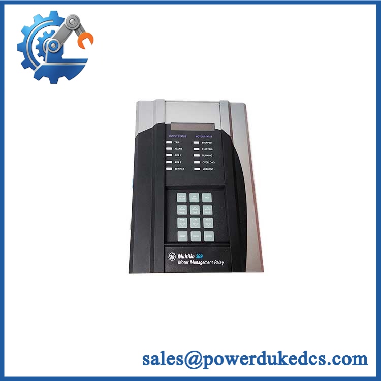
GE 369
Application Scenarios & Pain Points
Motor feeder protection: On a medium-voltage motor feeder, the 369 can continuously evaluate phase current and thermal loading while responding to conditions such as overload, short circuit, ground fault, unbalance, and other configured protection elements.
Pump and compressor applications benefit from the relay’s motor-management functions, particularly where process equipment requires both protective trips and pre-trip alarm information. The exact enabled functions depend on the ordered hardware and configuration.
For high-inertia loads, mechanical-jam and locked-rotor functions can be important because an electrical fault is not the only mechanism that can damage a motor. The protection model must be configured from the motor’s actual nameplate and starting characteristics rather than copied from another installation.
In plants with legacy SCADA systems, the rear RS-485 interfaces and Modbus RTU support can preserve existing communications architecture. One installation may use multiple serial connections for control-system integration, while another may have an optional Ethernet or fieldbus interface.
At elevated cabinet temperatures, validate the enclosure environment before installation. The original relay qualification and equipment specifications should govern the actual operating limit; do not substitute a generic PLC temperature rating for the 369.
🚨 Common Error Codes & Diagnostic Symptoms
The 369 documentation uses relay status, alarms, trips, and self-diagnostic indications rather than one universal “369 hardware failure code.” Therefore, a displayed protection trip should not automatically be interpreted as a defective relay.
Symptom: SERVICE indication / self-diagnostic failure → Diagnosis: The relay’s internal diagnostics have detected a service condition, or the unit is in a test/service state; verify the displayed diagnostic information and external conditions before condemning the hardware → Action: Review the self-diagnostic result, confirm control power and wiring, then replace the relay if an internal hardware fault is established.
Symptom: Display or keypad unavailable with verified control power → Diagnosis: An internal electronics, display-interface, or control-power problem is possible after external supply and wiring have been ruled out → Action: Verify the correct LO/HI power class and supply levels, then replace the complete relay if the internal fault is confirmed.
Symptom: RS-485/RS-232 communication repeatedly drops while protection remains operational → Diagnosis: Address, baud rate, parity, cabling, termination, grounding, or external master configuration should be checked before assuming a relay failure → Action: Validate the serial network first; replace the 369 when internal communications hardware is demonstrated to be defective.
🚨 Cross-Reference & Lifecycle Migration
Exact Model and Variant Control
GE 369 is a platform family, not a complete ordering description. The relay is available in different control-power and option configurations, so the full nameplate ordering code should be captured before sourcing a replacement. The documented power classes include:
- LO: 24–48 VAC/DC
- HI: 100–240 VAC or 110–250 VDC
A replacement should therefore match the installed unit’s control-power class, CT arrangement, I/O configuration, communications options, and firmware requirements.
Firmware and Compatibility
GE officially documents firmware 3.63 for the Multilin 369, released June 15, 2017. The release is installable through EnerVista Launchpad, with GE also providing a direct download and installation procedure.
Do not assume that every legacy 369 has version 3.63 installed. Check the actual relay firmware identification before a board or relay replacement, especially where newer communications or configuration functions are being used.
Migration Path
GE Vernova states that manufacturing of the 369 has been discontinued and identifies the Multilin 859 as its alternative.
The migration path has an important physical advantage: GE states that the 859 was designed as a direct replacement for the 369, with the same mechanical cutout, depth, and terminal arrangement, allowing existing 369 field wiring to be retained under the specified retrofit process. GE’s retrofit documentation still requires the panel and wiring to be de-energized and all applicable safety procedures followed.
Lifecycle Status
Lifecycle: Legacy / Obsolete — Manufacturing Discontinued.
For plants with multiple installed 369 relays, inventory should be handled as controlled legacy stock. Capture each unit’s complete ordering code, firmware, CT configuration, control-power range, communications options, and condition; a generic “369” warehouse description is not sufficient for a shutdown-critical spare.
Field Engineer’s Tech Notes
First warning: verify the control-power class before connecting anything. A 369 HI relay and a 369 LO relay are not interchangeable from a supply-voltage standpoint. Applying the wrong supply can damage the relay before any configuration work begins.
Second warning: do not copy CT settings from the old relay by memory. The 369 accepts 1 A and 5 A CT secondaries, and the configured CT primary value directly affects protection calculations. Photograph the old settings and confirm them against the motor protection study before commissioning.
Also check serial-line grounding. A communications fault may disappear during a bench test and return after the relay is connected to a long RS-485 cable because the cabinet grounding and cable shield arrangement changed.
Strict QA & Testing SOP
1. Inbound identity check
Record the complete 369 ordering code, serial number, hardware revision, firmware version, control-power class, and communications options.
2. Physical inspection
Examine the front display, membrane keypad, enclosure, terminal connectors, rear communication ports, mounting points, and labels. Look for cracks, corrosion, overheated areas, missing screws, and evidence of previous repair.
3. Power-stage inspection
Before energizing, verify that the relay’s actual control-power version matches the planned test supply. Perform appropriate pre-power resistance checks according to the applicable GE service documentation.
4. Controlled power-up
Apply the correct LO or HI supply using protected laboratory/test equipment. Confirm startup sequence, display operation, keypad response, status indicators, and self-diagnostic behavior.
5. Communications test
Test the front RS-232 and applicable rear RS-485 interface. Verify address, baud rate, parity, stop bits, protocol response, and communication stability.
6. Current-input simulation
Inject controlled 1 A or 5 A CT-equivalent signals through suitable test equipment. Confirm metering accuracy, phase identification, and representative protection-element operation.
7. Protection-function verification
Where the customer’s configuration is available, test the enabled protection elements against approved commissioning values. Avoid using generic trip settings because the relay is heavily dependent on the motor’s CT ratios, nameplate data, and protection study.
8. Event and alarm check
Confirm alarm/trip records, relay outputs, front-panel status, and communications reporting.
9. Final preservation
Once passed, record the test results and firmware version, then package the relay in ESD protection with mechanical cushioning and moisture control.
Test videos are available for live functional verification when the buyer requires visual evidence of the inspection.
Buyer’s FAQ
Is “GE 369” enough information to order a replacement?
Not for a controlled replacement. The 369 platform has multiple control-power and option configurations. At minimum, request the complete nameplate ordering code, control-power class, CT rating, communications options, firmware version, and actual relay photographs before procurement.
Can the 369 be hot-swapped?
Do not treat it as a routine hot-swap device. The relay can operate from control-power ranges reaching 250 VDC or 240 VAC, and its field terminals may connect directly into a motor protection circuit. GE’s 369-to-859 retrofit documentation explicitly states that the panel and wiring must be de-energized and safety procedures followed.
How do I verify a New Original 369?
For obsolete equipment, inspect the actual relay rather than relying on a stock photograph. Request clear images of the GE/Multilin nameplate, complete ordering code, serial/date information, front panel, rear terminal arrangement, and original packaging. The warranty should identify the condition sold, test scope, serial number, and warranty duration.
What happens when the 369 is no longer available?
GE Vernova currently identifies the 369 as Legacy and states that manufacturing has been discontinued. Its published migration route is the Multilin 859, which was designed to use the same 369 mechanical cutout, depth, and terminal arrangement.
For long-term asset control, keep the installed 369 ordering code, firmware revision, CT settings, control-power class, I/O configuration, communications settings, and tested spare status in the maintenance database. This information becomes part of the migration package as well as the replacement record.











 Start Chat


