

Description
- Model: 50510-113-0000
- Brand: GE-associated industrial computing/control hardware
- Series: VME industrial computer and control architecture
- Part Type: 13-slot VME J1-Bus backplane board
- Core Function: Provides the physical VMEbus J1 backplane interconnection for compatible processor, I/O, and interface boards installed in a VME chassis.
- Key Specs: 13 VME slots, J1 backplane bus, passive backplane architecture, approximately 0.20 lb / 0.09 kg reported unit weight. Current market records identify the exact part as a 13-slot VME J1-BUS backplane board and classify it under PC board/computer hardware.
Product Introduction
A VME system can have perfectly functional processor and I/O boards yet remain unusable when the backplane has a damaged bus trace, oxidized connector, fractured solder joint, or failed mechanical interface. 50510-113-0000 is identified in current industrial records as a 13-slot VME J1-Bus backplane board, making it a rack-level interconnection component rather than a processor or intelligent I/O module.
That distinction changes the replacement inspection. There is no application firmware to match on the backplane itself; the important controls are the VME slot count, J1 connector arrangement, mechanical dimensions, mounting pattern, and electrical continuity of the bus. One current listing identifies the exact part as discontinued and another commercial source associates it with GE VMIVME equipment, but a GE OEM drawing for the exact part was not located in the reviewed public material.
Core Technical Specifications
| Parameter | Value |
|---|---|
| Manufacturer / Brand Reference | GE-associated industrial VME hardware |
| Part Number | 50510-113-0000 |
| Product Type | VME Backplane Board |
| Backplane Bus | VME J1-Bus |
| Number of Slots | 13 |
| Architecture | VMEbus industrial computer/control chassis |
| Board Function | Passive electrical interconnection between VME modules |
| Processor Included | No |
| I/O Included | No |
| Application Memory | None on the backplane itself |
| Firmware | None on the passive backplane |
| Network Interface | None as an independent backplane function |
| Power Conversion | Not identified; chassis-level supply is external to the passive board |
| Approximate Listed Weight | 0.20 lb / 0.09 kg |
| Exact Dimensions | Not verified from an OEM mechanical drawing |
| Mounting | VME chassis/backplane assembly |
| Slot Interface | VME module card positions |
| Lifecycle | Discontinued according to current commercial records |
The strongest part-specific evidence identifies 50510-113-0000 as a 13-slot VME J1-Bus backplane and reports a listed weight of 0.20 lb.
Do not assign a CPU memory figure, scan time, firmware revision, or processor power rating to this part. Those specifications belong to the VME boards installed behind the backplane.
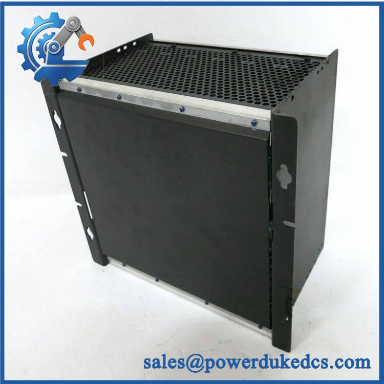
GE 50510-113-0000
Application Scenarios & Pain Points
Micro-case — intermittent VME system resets. A maintenance team may spend hours replacing processor boards before discovering that the real issue is an intermittent backplane connector or bus connection. On a legacy VME chassis, every slot depends on the physical integrity of the backplane.
In industrial computing systems, the 13-slot arrangement provides the physical positions for compatible VME modules. A replacement with a different slot count may fit the cabinet while still creating an engineering mismatch.
For legacy GE VME control platforms, this part is relevant when the original backplane develops cracked solder joints, damaged connectors, corrosion, or mechanical wear. Commercial records also associate the part with GE VMIVME equipment, although that association should be confirmed against the installed chassis documentation before substitution.
In high-temperature cabinets, inspect connector retention and board condition after prolonged operation above 50°C. Repeated thermal cycling can aggravate older solder joints and mechanical interfaces even when the attached VME modules remain electrically functional.
🚨 Common Error Codes & Diagnostic Symptoms
This is a passive backplane, so it has no independent firmware fault-code system. Failures normally present as system-level symptoms.
Symptom/Code: Multiple VME modules disappear simultaneously → Diagnosis: Possible loss of a shared backplane supply path, damaged bus connection, connector contamination, or cracked solder/interconnect joint. → Action: Isolate the chassis, inspect the backplane, and replace it after confirming the common fault follows the board.
Symptom/Code: Intermittent system resets when a particular slot is exercised → Diagnosis: Possible mechanical connector damage, poor card seating, or an intermittent backplane trace associated with that slot. → Action: Inspect the affected slot and card-edge interface; replace the backplane when the fault is confirmed at the slot level.
Symptom/Code: One or more VME modules fail to establish bus communication → Diagnosis: A local J1 connector problem, bent contacts, contamination, or an open/shorted backplane conductor can prevent proper VMEbus operation. → Action: Test bus continuity and connector condition before replacing the processor or I/O module.
🚨 Cross-Reference & Lifecycle Migration
Cross-Reference
The available records identify 50510-113-0000 specifically as a 13-slot VME J1-Bus backplane board. A separate industrial listing associates the exact number with GE VMIVME-3GE equipment.
That second association should be handled as a system-identification clue, not a universal replacement statement. No reliable evidence was located proving that another GE 13-slot VME backplane is a direct drop-in replacement.
When approving a substitute, verify:
- Number and position of slots
- J1 connector arrangement
- J2/J3 population, if applicable
- Backplane mounting-hole pattern
- Chassis depth and card-guide geometry
- Power-distribution arrangement
- Rear wiring and auxiliary connectors
Firmware Requirement
No firmware flashing is required for the passive backplane itself.
Firmware remains a property of the processor, communication controller, or intelligent VME module installed in the chassis.
Lifecycle Status
Status: Discontinued / Legacy
A current commercial record explicitly describes 50510-113-0000 as discontinued by the manufacturer.
For sites still dependent on this VME architecture, this status supports maintaining a controlled spare. Keep the exact part number in the inventory master and record the slot count and J1-bus identity so a visually similar VME backplane is not issued incorrectly.
Field Engineer’s Tech Notes
Warning 1 — Do not diagnose a VME bus fault by repeatedly reseating cards.
Repeated insertion can accelerate connector wear and scrape oxidation across already-aged contacts. First inspect the card edge, backplane connector, retaining hardware, and chassis alignment.
Warning 2 — Verify the chassis power distribution before condemning the backplane.
A failed chassis supply or overloaded rail can produce symptoms that look exactly like a damaged bus board. Measure the approved supply rails under load and verify the fault is actually localized to the backplane (especially when several modules fail together).
Strict QA & Testing SOP
Step 1 — Part identity check
Verify 50510-113-0000 from the actual board marking. Record any secondary assembly number, revision, serial number, and manufacturing/date information.
Step 2 — Mechanical inspection
Inspect the PCB, mounting holes, card guides, connector brackets, standoffs, and edge-support hardware for cracks or deformation.
Step 3 — Connector inspection
Examine every VME slot connector for bent contacts, contamination, corrosion, foreign material, or uneven mechanical alignment.
Step 4 — Visual PCB inspection
Check solder joints, copper traces, connector soldering, fasteners, and any signs of thermal damage or previous repair.
Step 5 — Continuity testing
With the board completely isolated, perform controlled continuity checks on the relevant VME J1 bus paths and chassis power-distribution connections according to the approved VME backplane test procedure.
Step 6 — Isolation checks
Where supported by the engineering test specification, check for unintended shorts between adjacent bus lines and between relevant power/ground paths.
Step 7 — Live-rig test
Install the board in a compatible VME chassis with known-good processor and I/O modules. Verify that every populated slot can establish expected bus operation.
Step 8 — Slot verification
Exercise multiple card positions and confirm that faults do not follow a particular backplane slot.
Step 9 — Thermal observation
Run the chassis under representative load and monitor for intermittent behavior, abnormal heating, or instability.
Step 10 — Documentation and packaging
Record the part number, revision, test results, photographs, and physical condition. Package the backplane in ESD-protective material with rigid support around connectors and mounting hardware.
Test videos are available for applicable units that undergo a compatible VME live-rig test.
Buyer’s FAQ
Can I hot-swap the 50510-113-0000?
Do not assume that the backplane itself is hot-swappable. It is a chassis-level interconnection board, and removal normally requires the VME system to be placed in the approved safe maintenance state. Follow the host equipment procedure and remove power before disconnecting the backplane unless the original system documentation explicitly permits energized service.
How do I verify a New Original unit?
Request photographs of the actual 50510-113-0000 board, including the part marking, connector population, slot count, mounting pattern, and overall PCB condition. Because the part is identified as discontinued in current commercial records, physical identity and condition records are particularly important.
What HS tariff code should I use?
The correct HS classification depends on the importing country’s tariff schedule and how the customs authority classifies a VME backplane board. Do not copy a generic PCB or computer-part code without broker confirmation.
For the commercial invoice, describe the item by its actual function: 13-slot VME J1-Bus backplane board for industrial computer/control chassis.
Does the board include firmware or the latest software?
No. The 50510-113-0000 is a passive backplane and does not carry the application firmware associated with VME processors or intelligent modules. The software state of the installed VME CPU should be documented separately.
What warranty should I expect?
Warranty depends on the supplier’s written terms and the condition category of the unit. For discontinued hardware, obtain the warranty period, test scope, return conditions, and actual-board photographs before purchase. A seller warranty should not be represented as an OEM factory warranty unless separately documented.











 Start Chat


