

Description
-
- Model: GE 8106-TI-RT
- Brand: GE Intelligent Platforms
- Series: PAC8000 Modular I/O
- Part Type: 4-channel analog RTD/resistance input module
- Core Function: Converts RTD or resistance measurements into digitized process data for transmission across the PAC8000 Railbus.
- Key Specs: 4 inputs; 2-, 3-, or 4-wire RTD support; Pt100, Ni120 and jPt100; 15 bits plus sign bit; 200 µA nominal excitation; 250 VAC rms channel-to-Railbus isolation; 42 mm module width; 200 g weight.
Product Introduction
The GE 8106-TI-RT is installed as a dedicated temperature/resistance input module within the PAC8000 Modular I/O architecture. Four independent channels accept RTD or resistance inputs, with support for 2-, 3-, and 4-wire RTD connections. The module digitizes those measurements and makes the resulting values available to the controller through the 12 V Railbus.
For maintenance and compliance records, the field terminal is part of the physical installation rather than an incidental accessory. GE specifies the 8606-FT-RT field terminal for the module, including applications in safe areas and applicable Zone 2/Division 2 hazardous-area configurations. Keep the module number, field-terminal identity, mechanical keying, and hazardous-area documentation together (this is particularly important when replacing older PAC8000 nodes).
Core Technical Specifications
Parameter Value Manufacturer GE Intelligent Platforms Catalog Number 8106-TI-RT Product Family PAC8000 Modular I/O Module Type 4-channel analog RTD/resistance input Number of Channels 4 Input Type RTD or resistance source RTD Wiring 2-wire, 3-wire, or 4-wire Supported RTDs Pt100, Ni120, jPt100 Pt100 Range −200 to +850°C jPt100 Range −200 to +510°C Ni120 Range −80 to +320°C Resistance Range 0–500 Ω span RTD Excitation Current 200 µA nominal Resolution 15 bits + sign bit Accuracy at 25°C ±0.05% of span Accuracy, +10 to +40°C ±0.1% of span Accuracy, −40 to +70°C ±0.2% of span Common-Mode Rejection >80 dB @ 50/60 Hz Series-Mode Rejection >40 dB @ 50/60 Hz Channel-to-Railbus Isolation 250 VAC rms Open-Circuit Bleed Current 0.5 µA nominal Open-Circuit Detection ≤10 s Signal Availability on Railbus 180 ms minimum; 840 ms maximum Input Filtering Off / 2-reading average / running average Open-Circuit Response Disabled / upscale Alarms High and low Channel Status Active / inactive Railbus Supply 12 VDC Railbus Current 150 mA typical / 200 mA maximum Bussed Field Power Not required Module Key Code C3 Module Width 42 mm Module Weight 200 g Recommended Field Terminal 8606-FT-RT Hazardous-Area Application Safe area or applicable Zone 2 / Division 2 Operating Temperature −40 to +70°C These values come from the published 8106-TI-RT module specification and PAC8000 documentation.
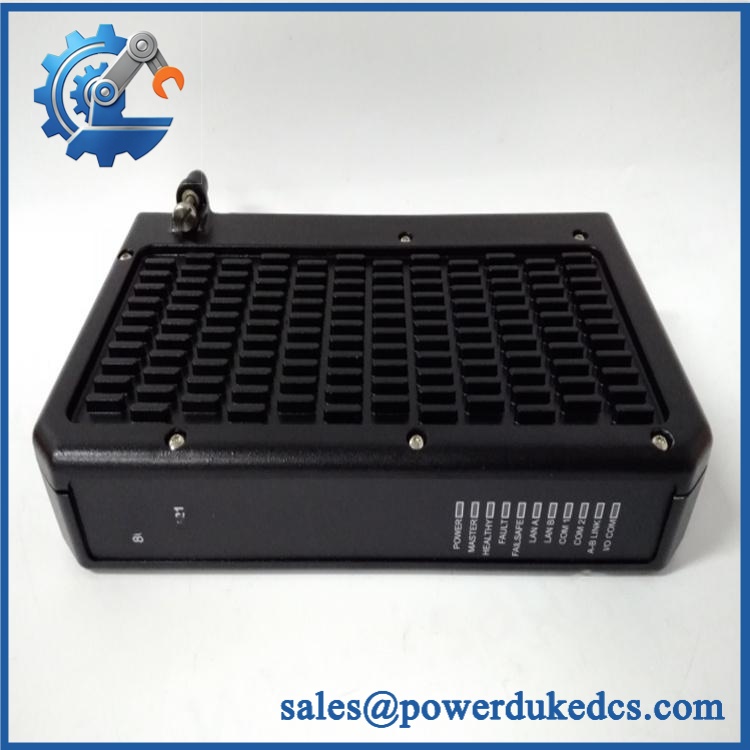
GE 8106-TI-RT
Application Scenarios & Pain Points
A temperature loop begins drifting while the RTD itself passes a resistance check. The 8106-TI-RT provides a useful isolation point for troubleshooting because the sensor, field terminal, module channel, and Railbus path can be tested separately.
In process plants, Pt100 measurement can cover −200 to +850°C, while Ni120 and jPt100 have their own narrower ranges. Selecting the correct sensor type is therefore part of the engineering configuration, not merely a field-wiring detail.
For machinery monitoring, the three available wiring methods allow engineers to choose the appropriate RTD connection for installation conditions. Three-wire and four-wire arrangements can reduce the effect of lead resistance compared with a simple two-wire connection.
Within hazardous-area projects, the module is documented for safe-area or applicable Zone 2/Division 2 arrangements when used with the specified field-terminal and system requirements. The installation approval applies to the complete arrangement, not simply to the catalog number printed on the module.
At 50°C+ ambient temperatures, the accuracy specification changes with temperature. GE’s published figures move from ±0.05% of span at 25°C to ±0.2% of span over −40 to +70°C, so plant acceptance criteria should use the appropriate environmental condition.
🚨 Common Error Codes & Diagnostic Symptoms
The published 8106-TI-RT documentation does not define a universal numerical error-code list for the individual module. Troubleshooting should therefore begin with channel status, sensor continuity, field wiring, Railbus behavior, and module diagnostics.
Symptom/Code: Open-circuit RTD indication → Diagnosis: The module can detect an open sensor circuit within 10 seconds or less; a broken RTD element, loose terminal, damaged cable, or incorrect termination can trigger the condition → Action: Check the complete sensor loop first, then replace the module if the fault persists with a known-good RTD and wiring.
Symptom/Code: Temperature reading fixed, implausible, or unstable → Diagnosis: Possible RTD type mismatch, incorrect 2/3/4-wire configuration, excessive lead resistance, field-terminal problem, or damaged input electronics → Action: Test the channel using a calibrated resistance source and compare the result with a known-good channel.
Symptom/Code: Several channels fail simultaneously → Diagnosis: A common Railbus, carrier, field-terminal, or module-level issue is more likely than several independent RTD failures → Action: Check the 12 V Railbus and carrier first, then substitute a verified module.
🚨 Cross-Reference & Lifecycle Migration
Exact Part Identity
The correct functional identification is:
GE 8106-TI-RT — 4-channel RTD and resistance input module.
The recommended field terminal is:
8606-FT-RT
The published documentation identifies this terminal for the 8106-TI-RT and specifies its use in both general-purpose and applicable hazardous-area installations.
Do not substitute an 8105-TI-TC thermocouple module simply because both are temperature modules. The sensor interface and electrical measurement method are different.
Firmware Requirement
The 8106-TI-RT is an I/O module rather than a standalone programmable controller. No conventional user firmware-flashing procedure is specified in the module documentation.
Configuration concerns instead include sensor type, input filtering, open-circuit response, alarm thresholds, deadband, and channel status.
Lifecycle Status
Lifecycle: Active in published MTL documentation, but legacy relative to newer control platforms.
Current Eaton/MTL documentation continues to publish specifications for 8106-TI-RT, while the module remains part of the older architecture.
For plants that still operate nodes, spare strategy should preserve the exact module number, C3 key code, compatible field terminal, and applicable hazardous-area documentation.
Field Engineer’s Tech Notes
First warning: verify the mechanical keying before insertion. The 8106-TI-RT uses key code C3. mechanical keying helps prevent installation of a module into an incompatible terminal arrangement. Never defeat that keying to force a fit.
Second warning: do not troubleshoot RTD accuracy without confirming the wiring method. A two-wire sensor introduces lead resistance that can become significant over long cable runs. Before declaring an input card faulty, confirm the actual sensor type and 2-, 3-, or 4-wire termination.
Keep the 8606-FT-RT field terminal with the spare whenever possible. This preserves the intended mechanical and field-wiring interface.
Strict QA & Testing SOP
1. Inbound identity check
Verify 8106-TI-RT on the physical label. Record serial/date information, hardware revision, module key code, and packaging condition.2. Mechanical inspection
Check the 42 mm module body, connector surfaces, keying features, housing, labels, and mounting interface for damage or contamination.3. Field-terminal verification
Confirm the associated 8606-FT-RT terminal and verify that the mechanical keying corresponds to the module.4. Railbus inspection
Verify the 12 V Railbus supply and carrier condition. The documented module current is 150 mA typical and 200 mA maximum.5. RTD simulation
Connect a calibrated RTD simulator or precision resistance source to each channel. Test representative values across the customer’s intended operating range.6. Wiring-mode test
Verify the required 2-wire, 3-wire, or 4-wire configuration. Confirm the expected lead-resistance compensation behavior.7. Sensor-type verification
Test Pt100, Ni120, or jPt100 behavior as applicable to the installed process. Confirm that the configured sensor type matches the customer’s engineering documentation.8. Accuracy verification
Compare measured values against the published temperature-dependent limits: ±0.05% span at 25°C, ±0.1% from +10 to +40°C, and ±0.2% from −40 to +70°C.9. Open-circuit test
Introduce a controlled sensor open circuit and verify the configured response. The published detection time is ≤10 seconds.10. Railbus communication test
Verify that all four channel values and status information are correctly delivered to the controller.11. Isolation verification
Where the test system permits, verify the documented 250 VAC rms channel-to-Railbus isolation using an approved procedure.12. Final packaging
Place the module in ESD-safe protective packaging, protect the connector, retain the field-terminal information, and attach the QC record.Test videos are available when live functional verification is performed and visual evidence is required for procurement approval.
Buyer’s FAQ
Is 8106-TI-RT a 4–20 mA input module?
No. It is specifically an RTD and resistance input module. It has four channels and supports Pt100, Ni120, jPt100, and 0–500 Ω resistance measurement.
Can I use another field terminal?
Do not assume compatibility. GE specifies 8606-FT-RT for this module. The mechanical key code and field-terminal arrangement are part of the intended installation.
Can the 8106-TI-RT be hot-swapped?
Do not interpret its plug-in construction as unrestricted hot-swapping authorization. Follow the carrier and system maintenance procedure and the site’s electrical-safety requirements before removing or installing the module, particularly where field wiring enters a hazardous-area installation.
Does the module include the latest firmware?
The 8106-TI-RT is an I/O measurement module rather than a standalone controller with a user-managed firmware package. Its operating behavior is established through configuration, including sensor type, filtering, alarms, and open-circuit handling.
For New Original procurement, verify the actual module label, revision/date code, C3 key code, packaging condition, and compatible 8606-FT-RT terminal. For controlled inventory, retain the module identity, certification evidence, COO, inspection record, and storage condition as a single asset record.











 Start Chat


