

Description
- Brand: GE General Electric
- Full Model Number: DS215KLDCG1AZZ03A
- Lifecycle Status: Legacy / Obsolete
- Core Function: Mark V Key LED Display Card with firmware
- Top 3 Technical Specs: 32 display LEDs; 40-pin 3PL connector; 3 relays
- Functional Acronym: KLDC
- Functional Revision: A
- Artwork Revision: Z
- Assembly: DS215 special assembly
- PCB Coating: Normal coating
- Weight: Approximately 1.07 lb / 0.49 kg
- System: GE Speedtronic Mark V
- Stock & Condition: Exact physical stock and condition to be confirmed before PO; New Surplus or Tested Stock subject to quotation
GE documentation references and specialist technical listings identify the DS215KLDCG1AZZ03A as a Mark V KLDC Key LED Display Card and firmware assembly. The board is reported with 32 display lamps, a 40-pin 3PL connector, three relays, and two EPROM devices.
Obsolescence & Supply Chain Deep Dive
A failed KLDC card can become a procurement problem when a legacy Mark V cabinet has to remain operational without a broader controls migration. The DS215KLDCG1AZZ03A is not simply a generic display PCB: available technical records identify it as a Key LED Display Card and firmware assembly for the Mark V platform. Its 32 front-visible display lamps provide status information, while the board also contains processing and interface circuitry. Because Mark V hardware is a legacy platform, exact-revision inventory can be more practical than waiting for an OEM production route that may no longer exist.
The TCO case should account for turbine outage exposure, engineering labor, cabinet testing, emergency freight, and commissioning time. Replacing the failed board while retaining the existing Mark V architecture can avoid the substantially broader engineering scope of a complete control-system migration. This is particularly relevant when the installed system has remaining service requirements but a limited spare-parts pool. One important qualification: do not assume every KLDC or DS200KLDC variant is interchangeable; the DS215 assembly designation and ZZ03A suffix must be checked against the installed hardware and system documentation.
Compatibility & Replacement Matrix
| Approval Item | DS215KLDCG1AZZ03A Assessment | Buyer Action |
|---|---|---|
| Replacement Type | Drop-in hardware replacement only when the installed application calls for the same complete part number | Verify DS215KLDCG1AZZ03A before PO |
| Firmware | Board is identified as a card with firmware | Verify the installed firmware/configuration requirements before substitution |
| Hardware Modification | Normally not required for an exact part-number replacement | Match mounting, connector, and board configuration |
| Connector Interface | 40-pin 3PL connector identified | Confirm cable position and connector condition before installation |
| Display Interface | 32 display lamps identified as DS1–DS32 | Verify expected status indication after installation |
| Estimated Physical Replacement | Approximately 0.5–2 hours for qualified maintenance personnel | Excludes shutdown authorization and system commissioning |
| Commissioning | Required according to the site’s Mark V maintenance procedure | Confirm display, communication, and applicable control functions |
Field Traps — Watch Out
- Part-number and revision mismatch: The DS215KLDCG1AZZ03A is identified with functional revision A, artwork revision Z, and a special DS215 assembly. Do not substitute a DS200KLDC board merely because the KLDC designation is similar.
- 3PL connection error: The board uses a 40-pin 3PL connection strip. Label the existing cable before removal and verify connector orientation and pin condition during installation.
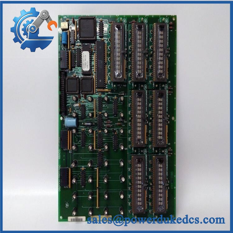
GE DS215KLDCG1AZZ03A
Quality Assurance & Testing SOP
For a legacy Mark V display and firmware card, QA should establish the exact board identity first, then verify the physical and functional elements that can affect installation.
- Part-number verification: Confirm the identification label reads and record all visible revision markings.
- OEM anti-counterfeit visual inspection: Inspect PCB artwork, GE identification labels, component markings, connector construction, solder quality, and evidence of unauthorized rework.
- Physical inspection: Check for corrosion, contamination, cracked components, damaged traces, bent connector pins, loose hardware, and coating damage.
- LED inspection: Verify the presence and physical condition of all 32 display lamps identified as DS1 through DS32.
- EPROM inspection: Check the two visible EPROM devices for physical damage, socket condition, and identification consistency with the required configuration.
- Relay inspection: Inspect all three relays for damaged housings, loose connections, discoloration, and overheating evidence.
- Connector inspection: Examine the 40-pin 3PL connector for bent pins, contamination, cracked housing, and secure board mounting.
- Power-on self-test: Where an approved Mark V test fixture is available, power the card under controlled conditions and verify expected display and diagnostic behavior.
- LED functional testing: Exercise applicable board functions and confirm expected DS1–DS32 indication against the approved Mark V test documentation.
- Interface testing: Verify the 3PL interface and applicable board communication paths using an approved Mark V test environment.
- Firmware verification: Record firmware/EPROM identification where applicable and compare it with the customer’s required configuration.
- Final QA record: Document the complete part number, revision, identification data, visual inspection, test results, date, and inspector approval before packing.
A generic power-on test should not be presented as proof of full Mark V system compatibility. The appropriate acceptance test is the one defined for the installed cabinet and application. The available technical record confirms the board’s 32 LEDs, two EPROMs, three relays, and 40-pin connector, but application-specific functional limits should be taken from the applicable GE documentation.
Procurement & Lifecycle FAQ
Is the GE genuinely in stock, and what is the cutoff for emergency shipping?
Specialist inventory listings currently show the exact , including listings marked in stock, but live inventory should still be confirmed against the physical unit before a PO is released.For emergency requirements, request confirmation of quantity, exact suffix, condition, test status, packing completion, carrier, and same-day shipping cutoff in the quotation.
How do you verify the condition and authenticity of an obsolete ?
Request actual-unit photographs showing the GE identification label, PCB markings, 3PL connector, LED array, EPROMs, and relays. The QA record should document visual inspection and functional testing where an appropriate Mark V test fixture is available. For New Surplus stock, ask the supplier to distinguish unused inventory from repaired or previously installed material.
Are there any firmware compatibility issues I should warn my engineers about before issuing the PO?
Yes. The board is specifically identified as a KLDCG1 card with firmware, and the exact ZZ03A configuration should be matched before installation. Do not assume that a physically similar KLDC board has equivalent firmware or application characteristics.
Is the a direct replacement for DS200KLDCG1AAA?
Do not approve that substitution without engineering verification. Public technical records identify the as a DS215 special assembly with its own revision and firmware designation, while DS200KLDC variants belong to a different assembly designation. The complete installed part number and Mark V documentation should control the replacement decision.
What are the warranty and return terms?
The quotation should state the warranty period, DOA coverage, return window, accepted condition, and functional-test coverage before the PO is released. For obsolete Mark V cards, specify whether the supplied unit is New Surplus, Tested Refurbished, or repaired stock, because those conditions can carry different inspection and warranty terms.











 Start Chat


