

Description
- Brand: GE Fanuc
- Full Model Number: IC670MDL930
- System/Series Family: GE Field Control Distributed I/O
- One-Sentence Core Function: 16-point relay output module for switching external AC or DC loads in a Field Control I/O station
- Top 3 Hardcore Specs: 16 relay outputs; 120 VAC nominal switching; 2 A resistive / 0.5 A inductive contact rating
- Stock Status: Stock condition and hardware revision to be confirmed
Module 3: Technical Product Introduction
When a Field Control station needs to switch real relay contacts rather than provide a semiconductor output, GE IC670MDL930 is the appropriate module class to examine. It provides 16 individually controlled relay output points within the GE Field Control Distributed I/O architecture. The relay contacts provide a physical switching interface to external circuits, making the module suitable for equipment commands, interposing relays, annunciation, and other discrete control functions where a dry-contact interface is required.
The electrical load specification matters more than the 16-point count. The relay outputs are designed for external circuits up to approximately 120 VAC, with contact ratings dependent on load type; resistive and inductive loads must be evaluated separately. Because relay contacts have mechanical switching characteristics, contact wear, inrush current, suppression, and switching frequency all affect field life. Exact contact ratings and permitted voltage/current combinations should be checked against the installed hardware revision and GE documentation before connecting a production load.
Module 4: Application Scenarios & Field Realities
- For motor starters and interposing relays, the IC670MDL930 provides a physical relay contact that can switch an external control circuit. Check the coil’s pickup current and inrush rather than sizing the circuit from the steady-state current alone.
- In legacy machine-control panels, the 16 relay points can handle equipment commands where a field device needs an isolated contact rather than a powered transistor output. The external circuit supplies its own voltage through the relay contacts.
- Where AC and DC field loads coexist, verify each circuit independently. Relay contacts can switch different external voltages, but the permitted current, load category, switching frequency, and suppression arrangement still need to remain within the applicable contact specification.
- During troubleshooting of an apparently dead output, check the Field Control station, BIU, terminal block, field supply, and relay contact state separately. A commanded output with no voltage at the load does not automatically mean the relay module has failed.
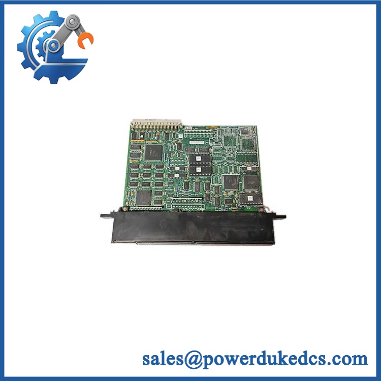
GE IC670MDL930
Module 5: Migration, Compatibility & Installation Traps
Replacement Matrix
Replacement Classification: Drop-in Replacement Within the Matching GE Field Control Relay-Output Configuration
A like-for-like IC670MDL930 replacement is appropriate when the existing Field Control installation uses the same relay-output architecture, compatible terminal block, BIU, cable assembly, and module keying. The field wiring must be retained according to the approved GE wiring arrangement.
IC670MDL930 → IC670MDL931: Hardware Modification Required. A related relay-output variant may use different contact arrangements or electrical ratings. Do not select solely by the common IC670MDL93x family designation.
IC670MDL930 → IC670MDL940: Hardware Modification Required. Semiconductor or different relay-output architectures can have different voltage, current, isolation, and switching characteristics.
→ Generic digital-output module: Hardware Modification Required. A transistor or solid-state output does not reproduce the relay-contact behavior of the .
⚠️ Field Traps — Watch Out
1. Relay-contact load type: Resistive and inductive loads impose different stress on relay contacts. Solenoid coils and contactor coils can generate significant switching transients, so external suppression should follow the approved circuit design.
2. Contact state and wiring: Verify the actual NO/NC contact arrangement and terminal assignment from the GE documentation for the installed revision. Never infer the contact topology from the output-channel number alone.
3. Inrush current: A load may draw substantially more current at energization than during steady-state operation. Check transformer, solenoid, contactor, or lamp inrush before connecting it to a relay output.
4. Field Control dependency: The is part of the complete Field Control I/O architecture. Verify the BIU, terminal block, cable assembly, and mechanical keying before installation.
Module 6: Quality Assurance SOP
Each GE should undergo a documented mechanical, relay-contact, electrical, and Field Control communication test before shipment.
- OEM identification visual inspection: Verify GE Fanuc markings, designation, serial number, hardware revision, module label, connector interface, and front-panel indicators.
- System verification: Confirm compatibility with the GE Field Control Distributed I/O architecture and record the associated BIU, terminal block, and cable configuration.
- Mechanical inspection: Examine the housing, connector, keying features, relay section, PCB, LED indicators, mounting surfaces, and accessible components for impact, corrosion, contamination, or evidence of repair.
- Power verification: Install the module in an approved Field Control test station and verify correct logic and field-power conditions.
- Power-on self-test (POST): Confirm normal initialization and verify module status through the associated BIU.
- 16-channel output test: Command each output individually and verify the corresponding relay operation and contact-state indication.
- Contact-continuity test: Measure each relay contact in its de-energized and energized states and record the observed resistance and switching condition.
- Contact-state verification: Confirm NO/NC terminal behavior against the approved GE wiring documentation for the applicable hardware revision.
- Voltage-switching test: Apply a controlled representative load voltage and verify reliable switching without excessive contact arcing.
- Load simulation: Test representative resistive loads and, where authorized, inductive relay loads within the applicable contact ratings.
- Inrush evaluation: For inductive or high-inrush loads, verify pickup behavior using a controlled test fixture and confirm that contact stress remains within the approved specification.
- Suppression verification: Confirm that the test load uses the required external suppression for coils or other inductive loads before repeated cycling.
- BIU communication test: Verify that output commands sent through the host/BIU reach all 16 channels correctly.
- Channel independence test: Operate individual relay outputs while monitoring adjacent channels for unintended switching or electrical interaction.
- Relay-cycle test: Repeatedly energize and de-energize representative outputs while monitoring contact stability, switching consistency, and abnormal heating.
- Extended stability test: Maintain representative loads for an extended operating period while monitoring relay contacts, field voltage, module status, and communication stability.
- Final QC record: Retain complete part-number photographs, hardware revision, terminal-block reference, all-channel relay tests, contact measurements, load-test conditions, BIU communication results, cycle-test results, and final QC approval.
The is a 16-point Field Control relay output module intended to provide discrete relay-contact switching within a GE Field Control Distributed I/O station. Unlike transistor-based output modules, its key functional characteristics are the mechanical relay contacts, external load switching, contact ratings, inrush capability, suppression requirements, and relay contact state.
For spare-parts control, verify the complete identification together with the BIU, terminal block, cable assembly, contact arrangement, field voltage, load type, and switching duty. The relay output should be tested under a representative load before being released for a production Field Control installation.











 Start Chat


