

Description
- Full Model Number: IS200TBCIS2CCD
- Lifecycle Status: Legacy / Obsolescence-Risk
- Core Function: Mark VIe contact input terminal board with grouped isolation
- Top 3 Technical Specs: 24 discrete inputs; 3 isolated groups of 8 channels; 125 VDC nominal field excitation
- Stock & Condition: New surplus / tested refurbished — verify terminal configuration, I/O pack pairing, and system architecture before PO
The IS200TBCIS2CCD is identified as a GE TBCI Contact Input Terminal Board for Mark VI/Mark VIe applications. Available technical references describe 24 dry-contact inputs and use with GE Mark VIe/Mark VIeS I/O hardware. In TMR applications, the board uses separate JS1, JT1, and JR1 connections; simplex operation uses the JR1 path.
Module 3: Obsolescence & Supply Chain Deep Dive
A failed IS200TBCIS2CCD can remove a large block of discrete field status signals from a turbine control system at once. This board is used to interface field contact devices such as switches and relay contacts with GE Mark VI-family controls, so a failure can affect permissives, interlocks, valve indications, breaker status, limit switches, and other sequence-related signals. The documented configuration provides 24 contact inputs, arranged in grouped isolation architecture.
From a TCO perspective, replacing the terminal board can preserve existing field wiring, controller hardware, I/O software configuration, cabinet layout, and commissioning records. Replacing the complete control platform for a terminal-board failure would introduce much higher engineering and outage costs. The key procurement issue is architecture matching: IS200TBCIS2CCD is not a generic digital-input board. Its grouped-isolation design, connector arrangement, field excitation requirements, and compatible I/O processor must match the installed system. That is especially important for TMR or safety-related installations.
Module 4: Compatibility & Replacement Matrix
| Procurement Check | IS200TBCIS2CCD Assessment | Engineering Action |
|---|---|---|
| Replacement Type | Drop-in Replacement for a matching TBCIS2C installation | Match complete part number and revision |
| Software Compatibility | Configuration-dependent | Verify I/O pack type, ToolboxST configuration, and channel assignments |
| Hardware Modification | Normally none for an identical installation | Confirm terminal blocks, connector arrangement, excitation voltage, and mounting |
| Typical Switch Time | Approx. 1–3 hours | Allow extra time for channel-by-channel verification |
| Estimated Engineering / Testing Cost | Approx. 400–1,500 | Include input simulation and diagnostic testing |
| Alternative | Different TBCI configuration or I/O architecture | Requires wiring and application review |
Field Traps — Watch Out
TMR versus simplex wiring: Technical references identify three rear connections — JS1, JT1, and JR1 — for TMR installations, while simplex systems use the JR1 connection. Do not copy a cable arrangement from a different Mark VI architecture without checking the installed configuration.
Input-voltage and isolation configuration: Published references identify this TBCI configuration with grouped isolation and a nominal 125 VDC excitation arrangement. Other TBCI variants can have different input configurations. Match the installed field supply and isolation architecture before energizing the replacement.
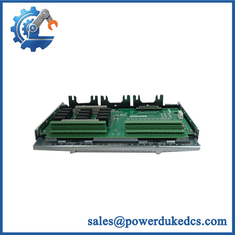
GE IS200TBCIS2CCD
Module 5: Quality Assurance & Testing SOP
The IS200TBCIS2CCD should undergo controlled electrical, configuration, and channel-level testing before shipment.
1. Incoming inspection
- Record manufacturer, complete part number, serial/date code, and revision markings.
- Perform OEM anti-counterfeit visual inspection.
- Inspect PCB surfaces, terminal blocks, connectors, jumper/header areas, mounting hardware, and isolation components.
- Check for corrosion, contamination, cracked components, damaged terminals, bent contacts, or unauthorized repair.
2. Configuration verification
- Confirm identification.
- Record functional, hardware, and artwork revisions.
- Verify the TBCIS2C grouped-isolation configuration.
- Confirm the 24-channel input arrangement.
- Document the required field-excitation voltage.
- Verify whether the installation is simplex, dual, or TMR.
- Photograph terminal and connector identification for traceability.
3. Electrical inspection
- Perform continuity testing on applicable input paths.
- Verify terminal-to-terminal isolation between the three input groups.
- Check connector pin integrity.
- Perform controlled insulation-resistance testing where applicable.
- Verify grounding and shield connections according to the approved procedure.
- Check field-excitation paths for unintended shorts.
4. Power-on and input testing
- Install the board with the compatible GE I/O processor or I/O pack.
- Apply controlled system power.
- Perform power-on self-test (POST) at the system level where supported.
- Verify hardware recognition and diagnostic status.
- Apply simulated dry-contact/open-contact states to representative input channels.
- Test all required 24 contact inputs individually.
- Verify ON/OFF state recognition at the host controller.
- Test grouped-isolation behavior between the three channel groups.
- Verify fault and diagnostic indications.
- Perform I/O load testing on applicable interface circuits.
- Run an extended input-state test to identify intermittent terminals or unstable channels.
5. Final QC
- Record all tested channels, isolation results, excitation conditions, revision, serial number, and test date.
- Confirm the supplied board matches the required Mark VI architecture.
- Generate a unit-specific Test Report.
- Verify terminal and connector integrity.
- Package using ESD and mechanical protection.
- Apply final QC identification before shipment.
Module 6: Procurement & Lifecycle FAQ
Is GE genuinely in stock, and what is the emergency-shipping cutoff?
Current commercial references show this part being offered as available inventory, but physical allocation should be confirmed against the actual board, revision, and condition before the PO is released. Emergency dispatch depends on QC completion, payment/order clearance, warehouse processing, and the courier cutoff.
How do you guarantee the condition and authenticity of surplus units?
Require complete part-number and revision verification, PCB and terminal inspection, grouped-isolation testing, controlled system power-up, all required input-channel checks, I/O processor recognition, and a unit-specific Test Report. Actual photographs of the supplied board should be retained with the procurement record.
Are there any firmware compatibility issues I should warn my engineers about before issuing the PO?
Yes. The terminal board itself is primarily hardware, but the associated I/O processor or I/O pack firmware and ToolboxST configuration can affect successful operation. Technical references also note that firmware may need to be downloaded for the unit to operate correctly in some installations. Record the existing I/O pack type, firmware revision, channel mapping, and project configuration before replacement.
Can I substitute another GE TBCI terminal board for ?
Not automatically. GE TBCI variants differ in input arrangement, isolation, terminal configuration, and system application. The is specifically associated with grouped-isolated contact inputs and can be used in simplex or TMR architectures. Match the complete board number and installed wiring before approving a substitute.
What warranty and return terms should procurement require?
Specify , serial number, complete revision marking, tested condition, applicable I/O processor configuration, warranty period, DOA criteria, acceptance window, and return procedure in the PO. Functional acceptance should include system recognition, all required contact-input channels, grouped-isolation verification, and stable operation under representative field-input conditions.











 Start Chat


