

Description
- Brand: GE Multilin
- Full Model Number: SR469-P5-HI-A20-E
- Product: 469 Motor Management Relay
- Lifecycle Status: Legacy product; current availability should be confirmed
- Core Function: Integrated motor protection, monitoring, and management
- Phase CT Input: 5 A secondary
- Control Power: 90–300 VDC; 70–265 VAC at 48–62 Hz
- Analog Outputs: 4–20 mA
- Front Panel: Enhanced display with larger LCD and improved keypad
- Communications: RS232 programming port; optional Ethernet or DeviceNet variants use different order codes
- Protection Scope: Thermal overload, current unbalance, phase reversal, overcurrent, voltage, frequency, and motor-specific protection functions
- Stock & Condition: Physical stock and condition to be confirmed per quotation; New Surplus or Tested Refurbished where available
- Supply Mode: Direct industrial spare-parts supply; emergency dispatch subject to confirmed inventory and carrier cutoff
The GE ordering code confirms that P5 specifies 5 A phase CT secondaries, HI specifies the high-range control power supply, A20 specifies 4–20 mA analog outputs, and E specifies the enhanced front panel.
Obsolescence & Supply Chain Deep Dive
A failed SR469 can affect far more than motor trip protection: it can remove thermal monitoring, current and voltage supervision, event information, control functions, and the operator interface from an installed motor protection scheme. The GE 469 is designed as an integrated motor protection and management relay, and GE lists the SR469-P5-HI-A20-E as a typical configuration for medium and large motor applications. Its P5/H I/A20/E configuration combines 5 A phase-current inputs, high-range control power, 4–20 mA outputs, and the enhanced front panel.
From a TCO perspective, an equivalent SR469 replacement can preserve the existing CT wiring, control-power arrangement, analog-output architecture, protection settings, and panel cutout rather than forcing a complete protection-system migration. GE documentation identifies the relay’s control power as 90–300 VDC or 70–265 VAC and provides a 4–20 mA analog-output option for the A20 configuration. The engineering review should still compare the complete order code, firmware revision, stored settings, communications arrangement, and installed application before the PO is released (especially important when sourcing older inventory with different production dates).
Compatibility & Replacement Matrix
| Replacement Scenario | Assessment | Engineering / Procurement Guidance | Estimated Switch Time |
|---|---|---|---|
| Identical SR469-P5-HI-A20-E replacing the installed unit | Drop-in Replacement subject to configuration verification | Match order code, CT rating, control power, analog outputs, front-panel option, and firmware | Approx. 2–6 hours |
| Same SR469 family with different firmware | Software Compatible — verification required | Compare firmware revision and configuration before restoring settings | Approx. 4–8 hours |
| with different CT or control-power option | Not automatically interchangeable | Verify CT secondary rating and supply range before energization | Approx. 4–8 hours |
| Different motor protection relay | Hardware Modification | Requires CT/VT, I/O, trip logic, communications, settings, and commissioning review | Several days to several weeks |
Field Traps — Watch Out
- P5 versus P1: P5 specifies 5 A phase CT secondaries, while P1 specifies 1 A. The installed CT secondary rating must match the replacement order code.
- HI control power: The HI version accepts 90–300 VDC or 70–265 VAC at 48–62 Hz. Do not substitute an LO version without confirming the actual control-power supply.
- A20 output configuration: A20 identifies the 4–20 mA analog-output option. If the plant DCS uses these outputs for motor monitoring, verify channel assignments and scaling after replacement.
- Firmware and settings: Record the existing firmware revision and protection settings before removing the failed relay. A model-number match alone does not guarantee identical configuration.
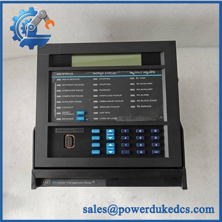
GE SR469-P5-HI-A20-E
Quality Assurance & Testing SOP
The should be tested as a complete motor-management relay. Visual inspection alone is insufficient for a protection device with CT inputs, analog outputs, digital controls, communications, and programmable protection functions.
- OEM anti-counterfeit visual inspection: Verify GE Multilin markings, identification, model/order code, labels, connectors, front-panel construction, and certification markings.
- Nameplate verification: Record -P5-HI-A20-E, serial number, firmware revision, manufacturing information, CT rating, and control-power information where available.
- Mechanical inspection: Check the enclosure, drawout mechanism, terminal blocks, front-panel keypad, LCD, connectors, and PCB assembly for damage or unauthorized modification.
- Power-on self-test (POST): Energize the relay under controlled conditions and verify startup diagnostics, LCD initialization, status LEDs, and absence of abnormal diagnostic messages.
- Display and keypad test: Verify the enhanced LCD, navigation keys, reset functions, and programmable control interface.
- CT input simulation: Apply controlled representative current signals to the phase-current inputs and verify measurement accuracy and correct phase identification.
- Voltage input test: Where applicable, inject controlled voltage signals and verify measurement, phase relationship, and configured protection responses.
- Protection-function testing: Test applicable thermal, overcurrent, current-unbalance, phase-reversal, voltage, frequency, and motor-specific protection elements against the approved test plan.
- Analog-output load testing: Verify the A20 4–20 mA outputs using calibrated measurement equipment and confirm expected scaling.
- Digital I/O load testing: Exercise applicable digital inputs and output contacts under controlled test conditions.
- RS232 communication test: Verify the programming/service interface and configuration communication where the test setup supports it.
- Event and diagnostic verification: Confirm that representative trips, alarms, and diagnostic records are generated and displayed correctly.
- Extended run test: Maintain controlled operation long enough to identify intermittent resets, display faults, communication interruptions, or abnormal heating.
- Final traceability: Photograph the actual relay, record serial and firmware information, document test results, and retain the inspection record with the shipment.
- ESD-safe packaging: Protect the relay against electrostatic discharge, shock, vibration, and moisture during transport.
Procurement & Lifecycle FAQ
Is the GE -P5-HI-A20-E genuinely in stock, and what is the cutoff for emergency shipping?
Physical inventory should be confirmed before the PO is accepted. For an emergency requirement, provide the quantity and destination so the actual unit, condition, test status, and carrier cutoff can be confirmed before dispatch.
How do you verify the condition and authenticity of an obsolete or surplus ?
The relay should undergo model and nameplate verification, physical inspection, controlled power-up, display and keypad testing, CT/VT simulation where available, digital I/O testing, 4–20 mA output testing, and applicable protection-function testing. Actual-unit photographs can also be provided for procurement review.
What does -P5-HI-A20-E mean?
The order code identifies a 5 A phase-CT version, HI control-power range, 4–20 mA analog-output configuration, and enhanced front panel. GE’s ordering documentation confirms these option definitions.
Are there firmware or configuration issues my engineers should check before issuing the PO?
Yes. Record the installed relay’s firmware revision, protection settings, CT/VT configuration, analog-output assignments, digital I/O logic, and communications parameters before replacement. GE documentation identifies firmware information as part of the relay’s product identification.
What warranty and return terms apply?
Warranty duration, return eligibility, and exclusions should be stated on the quotation according to the actual unit condition and testing status. These terms should be confirmed in writing before the PO is issued.











 Start Chat


