

Description
- Brand: GE Multilin
- Full Model Number: UR6EH
- System/Series Family: Multilin Universal Relay Series
- Core Function: Digital I/O expansion module providing contact inputs and relay outputs for GE Multilin UR protection systems
- Top 3 Hardcore Specs: 8 digital/contact inputs | 4 Form-C relay outputs | SPDT output configuration
- I/O Architecture: 8 inputs + 4 Form-C outputs
- Output Type: Form-C / SPDT
- Order Code: 6E
- Stock Status: New Surplus or Fully Tested Refurbished — confirm actual unit condition before purchase
Technical Product Introduction
A failed I/O card inside a protection relay can disable breaker-status monitoring, interlocking signals, alarms, or control commands even when the relay’s main processor remains operational. The GE UR6EH is a digital I/O module for the Multilin Universal Relay platform, providing 8 digital/contact inputs and 4 Form-C relay outputs. The 6E designation identifies this particular I/O configuration, allowing external field contacts and relay-controlled circuits to interface with the UR system.
The important distinction is channel architecture, not simply the model number. Four Form-C outputs provide both normally open and normally closed contact paths, while eight digital inputs accept external status or control contacts. That arrangement is useful where a single UR relay must monitor breaker auxiliary contacts and operate external control or alarm circuits. The module belongs to the UR Series I/O architecture, so replacement work should start by comparing the installed module’s order code and relay configuration rather than assuming that every UR-series I/O card is interchangeable.
Application Scenarios & Field Realities
- During breaker-status monitoring, the eight digital inputs can be assigned to external contact states such as breaker position, trip indication, or auxiliary alarm signals. Verify the actual input wiring and configured logic before moving conductors to a replacement card.
- For trip and control circuits, the four Form-C outputs provide changeover contacts that can interface with external control wiring. This is particularly useful where the existing panel logic depends on both NO and NC contact states rather than a single switching path.
- In substation automation panels, UR-series digital I/O modules are used to connect protection and control equipment with field devices. A failed UR6EH can therefore affect more than one indication point; several programmed logic paths may depend on the same I/O hardware.
- When maintaining legacy UR installations, keeping a matching I/O module as a controlled spare can reduce troubleshooting time. The replacement should be checked against the original hardware order code because GE offered several UR digital I/O configurations with different input/output arrangements.
Migration, Compatibility & Installation Traps
Replacement Matrix
| Replacement Condition | Assessment | Engineering Requirement |
|---|---|---|
| Existing module is GE UR6EH with the same I/O configuration | Drop-in Hardware Replacement | Verify order code, connector arrangement, relay configuration, and revision before installation |
| Replacement changes only hardware revision while retaining the required UR6EH I/O configuration | Software Compatible | Reload or verify the relay configuration if the host relay reports an I/O configuration mismatch |
| Replacing UR6EH with another UR I/O model having different channel architecture | Hardware Modification Required | Recheck every affected input/output assignment and control logic |
| Replacing with a different Form-A, SSR, or fast Form-C configuration | Not a direct replacement | Verify output contact behavior and external circuit requirements before substitution |
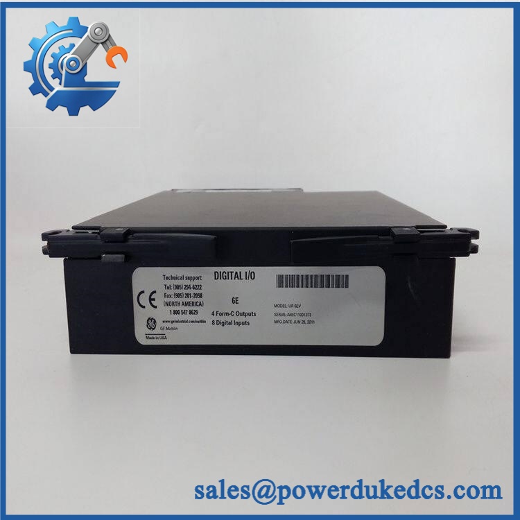
GE UR6EH
Field Traps — Watch Out
I/O configuration mismatch: UR-series digital I/O modules are differentiated by their order-code configuration. The 6E configuration corresponds to 8 digital inputs and 4 Form-C outputs. Installing a card with a different I/O architecture can change the available signal types and contact behavior.
Do not assume the replacement is configuration-free. Before removing the existing module, record terminal assignments, input states, output logic, and the host relay’s configuration. After installation, verify each input independently and test every programmed output under an approved maintenance procedure.
Power isolation matters. This is a relay-system I/O module, not a field-pluggable PLC slice that should automatically be treated as hot-swappable. Follow the applicable GE installation procedure and site lockout/tagout requirements before accessing the relay chassis.
Quality Assurance SOP
Before shipment, each available unit should pass a documented inspection sequence:
- OEM anti-counterfeit visual inspection — Compare the model marking, identification, labels, connectors, board construction, and visible manufacturing marks against the expected GE Multilin configuration.
- Hardware configuration check — Confirm the module corresponds to the 6E I/O configuration, including 8 digital/contact inputs and 4 Form-C outputs.
- Connector and PCB inspection — Examine edge connectors, terminal interfaces, PCB surfaces, mounting hardware, solder joints, and protective components for oxidation, physical damage, contamination, or previous repair evidence.
- Power-up diagnostic verification — When the module is tested within a compatible UR relay test setup, verify the host relay recognizes the installed I/O hardware and does not report an I/O configuration fault.
- Digital input verification — Apply controlled test signals to all available input channels and record the corresponding state changes in the host relay configuration or diagnostic interface.
- Form-C output verification — Test each of the four output channels for correct NO/NC changeover behavior. Confirm that the observed contact state corresponds to the programmed relay logic.
- Communication and configuration handshake verification — Confirm that the host UR relay recognizes the I/O module and that configured input/output points respond correctly during the test sequence.
- Functional alarm and logic check — Where the test setup permits, simulate representative breaker-status, alarm, and control signals without connecting the module to a live plant circuit.
- Final inspection record — Record the actual model, hardware revision, test observations, physical condition, and packaging condition. Photograph the nameplate and connector side before packing.
- Shipment release — Any mismatch between the physical unit and the ordered configuration stops shipment until the discrepancy is resolved.











 Start Chat


