

Description
- Brand — GE Fanuc / VMIC
- Full Model Number — VMIVME-2540-300
- System/Series Family — VMIVME-2540 Intelligent Counter/Controller
- Core Function — Intelligent VMEbus slave I/O board for precision event counting, timing, pulse measurement, frequency measurement, position measurement, and programmed waveform generation
- Top 3 Hardcore Specs — 24 configurable channels; 15 MHz 68HC000 local CPU; up to 4 giga-events per counter
- Stock Status — New Surplus or Tested Refurbished; exact condition to be confirmed before shipment
The VMIVME-2540-300 is the 24-channel configuration of the VMIVME-2540 family. The hardware manual identifies the -300 option as providing 24 channels, while the current product documentation describes the platform as a VMEbus slave I/O module with onboard processing and programmable measurement and signal-generation functions.
Technical Product Introduction
When a VME host has to supervise high-rate pulse streams, handing every timing operation back to the main CPU creates avoidable software overhead. The GE Fanuc VMIVME-2540-300 moves much of that work onto the board itself. Its 24 channels are handled through AM9513A System Timing Controllers, while an onboard 68HC000 processor running at 15 MHz provides the command-driven interface used to configure measurement, timing, and output functions. The board supports event counting, period and pulse-width measurement, frequency measurement, quadrature position measurement, delayed timing, and waveform generation.
The useful numbers are specific. Event counting reaches 32-bit operation with limits above 65,536, with the family supporting event counts up to 4 giga-events; period and pulse-width measurement can resolve signals from 400 ns upward, while square-wave and pulse-train generation extends to 2.5 MHz and frequency measurement also reaches 2.5 MHz. The local processor has 128 Kbytes of static RAM, and the VME interface supports a 64 Kbyte VMEbus memory window with configurable A24 or A32 operation. Compared with a basic VME digital I/O board that only exposes signal states to the host, the VMIVME-2540-300 performs measurement and timing functions locally, which can reduce host-side processing requirements.
Application Scenarios & Field Realities
- In automated test stands, the 24-channel configuration is useful when pulse trains, gates, clocks, and timing outputs have to be measured in parallel. The onboard timing controllers can perform measurements locally rather than requiring the VME host to sample every transition.
- For motion and position feedback, the quadrature position measurement mode supports sin/cos signals up to 1 MHz with 32-bit counters, along with limit and modulo checking. That matters when encoder feedback is part of a test or control sequence and the host must receive calculated position information rather than raw transitions.
- Where event timing is the actual measurement, such as trigger logging or equipment characterization, the board can allocate channels to event counting and delayed-event timing. The manual specifically allows any of the 24 channels to be configured for delayed-event timing, while 32-bit event counting uses even/odd channel pairs.
- For waveform-generation benches, the same board can generate square waves and pulse trains up to 2.5 MHz. That combination of measurement and generation in one VME slot can reduce external timing hardware — provided the existing application was designed around the command interface.
Migration Compatibility & Installation Traps
Replacement Matrix
| Replacement Case | Classification | Engineering Requirement |
|---|---|---|
| -300 replacing the same -300 | Drop-in Replacement | Match board revision, channel configuration, VME address settings, I/O connectors, and host software |
| -300 replacing another channel variant | Software Compatible | Review channel allocation and application configuration; -300 is specifically the 24-channel version |
| -300 replaced by a different VME counter or digital I/O architecture | Hardware Modification Required | Rework host addressing, driver interface, I/O wiring, timing configuration, and application logic |
The suffix is not cosmetic. The hardware manual shows -000 = 4 channels, -100 = 8 channels, -200 = 16 channels, and -300 = 24 channels through factory jumper selections. A different suffix therefore changes the available channel architecture even though the base name remains the same.
Field Traps — Watch Out
Channel-pair allocation: Several operating modes consume channels in pairs. The manual states that 32-bit event counting requires an even channel and the following odd channel to be allocated together. Quadrature operation also reserves a four-channel group. A software configuration that worked on another channel arrangement cannot simply be copied without checking allocation.
VME address configuration: The board can operate as an A24 or A32 VMEbus slave, with configuration controlled through jumpers. Supervisory and nonprivileged access can also be selected. Verify E52/E53/E54 against the existing chassis configuration before insertion; an address-space mismatch can make a functioning board appear dead to the host.
Connector wiring: The front-panel I/O uses DIN 41612 Type C 96-pin male connectors, with P3 and P4 each carrying 12 channels. The pinout includes differential clock, gate, output, ground, and VTTL connections. Do not transfer a cable based only on connector shape. Match the existing channel schedule pin by pin.
Power handling: The original manual specifically instructs maintenance personnel to disconnect power before component replacement or internal adjustment. as a powered-down VME installation unless the complete chassis documentation explicitly specifies another procedure.
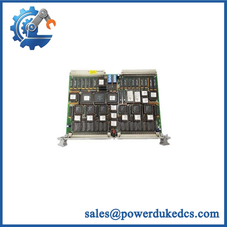
GE VMIVME-2540-300
Quality Assurance SOP
The pre-shipment proce should focus on board identification, VME operation, channel functionality, and timing performance:
- OEM anti-counterfeit visual inspection — compare the GE Fanuc/VMIC markings, model designation, PCB identifiers, revision markings, component population, connector construction, and evidence of unauthorized rework.
- Mechanical inspection — examine the VME card edge, P3/P4 connectors, mounting hardware, PCB surface, soldered components, and exposed contacts for corrosion, impact, contamination, or bent pins.
- Power-on self-test (POST) — install the board in an appropriate VME test chassis, monitor startup behavior, and check ERR/RUN or equivalent status LEDs where fitted. Record any abnormal initialization indication.
- VME host recognition verification — confirm that the host can access the board through the configured VME address space and that no bus timeout or address-decoding fault occurs.
- Channel function testing — exercise representative clock, gate, and output channels using controlled test signals. Confirm correct channel allocation and returned measurement values.
- Event counter verification — generate known pulse counts and compare the reported result with the test generator output, including rollover and limit behavior where applicable.
- Frequency and period verification — apply controlled reference signals and confirm measured frequency and timing values against the test instrument.
- Pulse-generation verification — command representative square-wave or pulse-train outputs and verify frequency and timing with an oscilloscope or frequency counter.
- Quadrature test — where applicable, apply a controlled quadrature source and verify direction and position-count response.
- Communication handshake verification — establish the VME host-to-board command/status exchange and verify command acknowledgement and returned measurement data.
- Configuration record — document the installed channel variant, VME address settings, jumper state, firmware/EPROM identification where visible, and test results.
- Final inspection and packaging — photograph the actual board, record serial and revision information where available, install ESD protection, protect connectors, and package the unit for industrial transport.
The manual provides unusually detailed acceptance-test opportunities because the local CPU, system timing controllers, VME command interface, and channel-control structures can all be exercised independently. For surplus inventory, a simple power-on check is not enough; the strongest verification is a controlled VME host transaction followed by known-frequency, pulse-count, and output-timing tests.











 Start Chat


