

Description
- Brand: Honeywell Analytics
- Full Model Number: 05701-A-0284
- Lifecycle Status: Obsolete
- Core Function: 5701 System 57 Catalytic Sensor Drive Module
- Top 3 Technical Specs: Constant-current catalytic sensor drive; 70–134 / 118–182 / 166–230 / 219–283 mA selectable ranges; 10 V maximum drive voltage
- Stock & Condition: New Surplus / Tested Inventory / Fast Dispatch subject to physical stock confirmation
Honeywell’s archived System 57 documentation identifies 05701-A-0284 specifically as the Sensor Drive Module, Catalytic, used with the 5701 control system. The module provides sensor power, acquires the catalytic sensor signal, and scales that signal for the control card.
Module 3: Obsolescence & Supply Chain Deep Dive
A failed Honeywell 05701-A-0284 can disable a catalytic gas-detection channel without requiring replacement of the complete System 57 rack. That creates a difficult sourcing situation for plants still operating legacy 5701 equipment: the sensor drive is a dedicated plug-in component, but it must match the catalytic channel architecture and the installed sensor configuration. Honeywell documentation specifies that the catalytic drive module plugs directly onto the channel control card and is factory configured for the required sensor drive range. Honeywell later documented the System 57 phase-out, with last-buy orders ending April 30, 2017 and planned spare support through April 30, 2022.
The TCO argument is straightforward when the existing detection rack, field wiring, and catalytic sensors remain serviceable. Replacing only the failed 05701-A-0284 can preserve the installed 5701 architecture instead of forcing a complete fire-and-gas controller migration, cabinet rework, engineering updates, and new commissioning activities. The module supports constant-current operation, with four documented current ranges and electronic adjustment in 1 mA steps; its maximum drive voltage is 10 V and maximum line resistance is 40 Ω including the sensor at 250 mA. For a legacy installation, those parameters matter more than simply finding a card with a similar form factor.
Module 4: Compatibility & Replacement Matrix
| Engineering Check | Assessment for 05701-A-0284 |
|---|---|
| Replacement Classification | Drop-in Replacement at Module Level when fitted to a compatible 5701 catalytic channel |
| Software Compatibility | No firmware flash normally required for the sensor drive module itself |
| Hardware Modification | Normally not required for a matching System 57 5701 assembly |
| System | Honeywell / Sieger System 57 5701 |
| Module Type | Catalytic Sensor Drive Module |
| Drive Method | Constant current |
| Current Ranges | 219–283 mA; 166–230 mA; 118–182 mA; 70–134 mA |
| Maximum Drive Voltage | 10 V |
| Maximum Line Resistance | 40 Ω including sensor at 250 mA |
| Full-Scale Signal Range | 15–600 mV |
| Typical Replacement Time | 30–90 minutes at module level, excluding isolation and calibration |
| Commissioning Requirement | Sensor-current verification, bridge-signal verification, zero/span calibration, alarm verification |
Honeywell specifies that the catalytic module is associated with the Single Channel Control Card Catalytic 05701-A-0302 and is connected directly to that card. The archived ordering information also identifies 05701-A-0284 as the catalytic sensor-drive component for the 5701 architecture.
⚠️ Field Traps — Watch Out
Catalytic drive-current mismatch: This is the primary engineering risk. Honeywell warns that incorrect sensor-drive current-range settings can cause permanent damage to the sensor. The available ranges are factory-set, and Honeywell states they should not be altered without reference to the System 57 technical documentation.
Sensor wiring and grounding: Sensor connections must be made with the System 57 unpowered, and the documentation warns that incorrect sensor wiring can damage both the sensor and the control system. Screened sensor cable is required for the specified EMC arrangement, with grounding handled according to the installation configuration.
Do not substitute the 4–20 mA module: 05701-A-0283 is the 4–20 mA Sensor Drive Module, while 05701-A-0284 is specifically the catalytic version. They are different functional configurations and should not be treated as interchangeable.
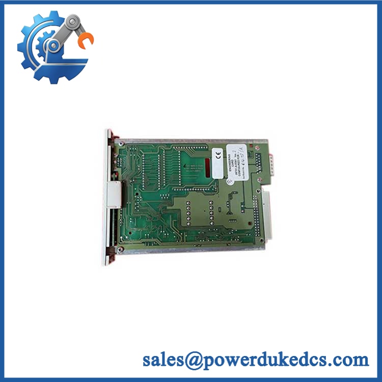
Honeywell 05701-A-0284 5701
Module 5: Quality Assurance & Testing SOP
For an obsolete 05701-A-0284, QA should verify the exact module configuration before it enters saleable inventory.
1. OEM anti-counterfeit visual inspection
Check Honeywell identification markings, 05701-A-0284 part number, PCB labeling, connector geometry, component population, mounting arrangement, and evidence of unauthorized repair. Capture high-resolution label and board photographs.
2. PCB and mechanical inspection
Inspect the board for corrosion, contamination, cracked solder joints, damaged connectors, lifted pads, burned components, and signs of overheating. Verify that the plug-in interface is mechanically sound.
3. Configuration-link verification
Inspect the catalytic current-range links before powering the unit. Confirm the physical configuration corresponds to the intended sensor application. Honeywell documents four current ranges and explicitly warns against changing the factory setting without technical reference.
4. Power-on self-test (POST)
Install the module on a compatible 5701 catalytic channel test assembly and apply controlled DC power. Verify normal channel startup and confirm expected Power On/Card Select, A1, A2, A3, Fault, and Inhibit indications at the channel-control-card level. Honeywell documents these channel indications as part of the 5701 control interface.
5. Catalytic bridge-current test
Measure the configured bridge current with calibrated instrumentation. Verify the selected range and confirm stable constant-current operation under representative sensor conditions.
6. Bridge-voltage and signal test
Connect a suitable catalytic sensor simulator or calibrated test arrangement. Verify the live bridge voltage and signal path. Honeywell specifies a full-scale signal range of 15 mV to 600 mV.
7. Fault-detection test
Simulate appropriate open-circuit and single-bead failure conditions where the test fixture permits. Confirm the channel recognizes the expected fault condition. The catalytic bridge specification includes open-circuit and single-bead fault detection.
8. Zero, span, and alarm verification
After the electrical test, perform the applicable zero and span calibration sequence and verify alarm operation through the complete channel assembly. Honeywell’s operating procedures include catalytic bridge-current adjustment, zero calibration, span calibration, and alarm testing.
9. Final QC record
Record part number, revision where present, serial or traceability information, current-range configuration, measured bridge current, signal results, test date, technician ID, photographs, and final QC disposition.
Module 6: Procurement & Lifecycle FAQ
Is the 05701-A-0284 genuinely in stock, and what is the cutoff for emergency shipping?
Physical availability must be confirmed against the exact 05701-A-0284 part number before PO acceptance. This is an obsolete System 57 spare, so procurement should treat existing inventory as finite. Honeywell’s archived material confirms the historical spare designation, while the System 57 product family has been phased out. Emergency orders should specify the physical stock quantity, tested condition, dispatch cutoff, and carrier service in writing.
How do you guarantee the condition and authenticity of an obsolete or surplus 05701-A-0284?
Require exact part-number verification, OEM marking inspection, PCB examination, configuration-link inspection, controlled power-up, catalytic bridge-current testing, signal verification, fault testing, and documented QC photographs. The unit should be tested as a 05701-A-0284 catalytic drive, not merely powered on as a generic System 57 board.
Are there firmware compatibility issues I should warn my engineers about before issuing the PO?
Firmware flashing is not normally the key concern for this module. The critical compatibility variables are the catalytic channel type, drive-current range, sensor type, line resistance, bridge signal range, and existing calibration configuration. Honeywell specifically warns that incorrect catalytic current settings can damage the sensor.
Can 05701-A-0284 replace a 05701-A-0283?
No. 05701-A-0284 is the catalytic Sensor Drive Module, while 05701-A-0283 is the 4–20 mA Sensor Drive Module. They support different sensor interfaces and should not be substituted based on physical fit alone.
What warranty and return terms should procurement require?
For surplus or refurbished inventory, the commercial terms should clearly state the warranty period, DOA coverage, return-authorization process, inspection window, and remedy for a failed unit. For this particular part, the warranty should cover the tested 05701-A-0284 module and its documented operating performance, including the agreed catalytic drive-current configuration.











 Start Chat


