

Description
- Brand: Honeywell Analytics / Sieger
- Full Model Number: 05701-A-0301
- Lifecycle Status: Obsolete / Legacy
- Core Function: Single-channel 4–20 mA gas detector control card
- Top 3 Technical Specs: 4–20 mA input; 18–32 VDC supply; 3.25 W typical power consumption
- Stock & Condition: New Surplus / Tested Refurbished; physical stock confirmation required; emergency dispatch subject to cutoff
Honeywell documentation identifies 05701-A-0301 as the Single Channel Control Card for 4–20 mA within the System 57 / 5701 control system. The card processes the sensor-drive signal, displays the measured level, evaluates alarm thresholds, and communicates alarm status to other cards.
Module 3: Obsolescence & Supply Chain Deep Dive
A failed 05701-A-0301 can remove an individual gas-detection channel from service even when the rest of the System 57 rack remains operational. This card is the dedicated 4–20 mA single-channel controller, combining signal processing, front-panel indication, alarm evaluation, and local control functions. Honeywell’s operating instructions state that the card is microprocessor-controlled, with its software configuration stored in EEPROM. That makes an exact spare particularly valuable where an installed System 57 system must remain in service without changing the existing detector architecture.
For TCO purposes, replacing one failed control card is normally more economical than redesigning an entire gas-detection installation. Existing field wiring, detector interfaces, rack infrastructure, alarm logic, and operating procedures can remain in place. The specified card also operates from 18–32 VDC and has typical 4–20 mA power consumption of about 3.25 W, making like-for-like replacement technically straightforward when the installed detector and sensor-drive configuration match. —Honeywell’s published System 57 documentation also shows that the platform is now legacy hardware, increasing the value of verified spare inventory.
Module 4: Compatibility & Replacement Matrix (Crucial for Buyers)
| Purchase / Migration Case | Compatibility Assessment | Typical Switch Effort |
|---|---|---|
| Replace an installed 05701-A-0301 with the same part number | Drop-in Replacement | 30–90 minutes |
| Replace with another 05701-A-0301 revision for the same System 57 application | Software Compatible — Verify Configuration | 1–2 hours |
| Substitute the catalytic 05701-A-0302 | Not a Direct Replacement | Engineering review required |
| Replace with a different System 57 control-card family | Hardware / Configuration Modification | 2–8+ hours |
| Migrate the channel to a newer gas-detection platform | Hardware Modification + Software/Configuration Change | 1–3+ days |
Honeywell explicitly distinguishes 05701-A-0301, the 4–20 mA single-channel control card, from 05701-A-0302, the catalytic version. Each uses the respective plug-in sensor-drive module, so the two part numbers should not be treated as interchangeable.
Field Traps — Watch Out
Sensor Drive Matching: The 05701-A-0301 is associated with the 4–20 mA sensor-drive arrangement, including sensor-drive module 05701-A-0283. Verify the sensor-drive module installed with the replacement card before approving the shipment.
Configuration Memory: The control-card software configuration is stored in EEPROM. A replacement card should therefore be checked for the required application configuration, alarm thresholds, detector settings, and engineering parameters before being returned to service.
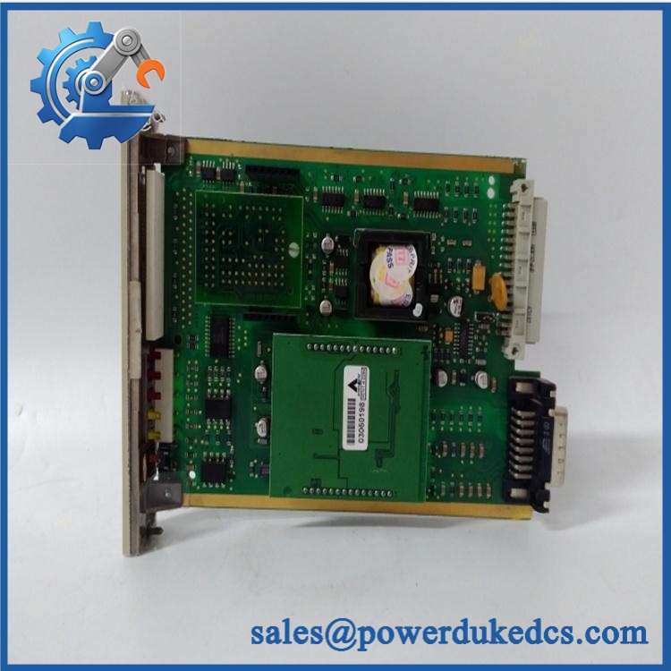
Honeywell 05701-A-0301
Module 5: Quality Assurance & Testing SOP
1. Part Identity Verification
Record the complete 05701-A-0301 part number, manufacturer markings, revision data, serial or lot information, and any PCB identification codes.
2. OEM Anti-Counterfeit Visual Inspection
Inspect the front-panel display, LEDs, push-buttons, card-edge contacts, connectors, PCB markings, labels, and manufacturing details. Compare construction against known System 57 hardware.
3. Mechanical Inspection
Check the PCB, front-panel assembly, mounting hardware, connector alignment, card guides, and edge contacts. Reject cards with corrosion, cracked solder joints, bent contacts, burn marks, or evidence of unauthorized repair.
4. Electrical Pre-Test
Verify supply and ground continuity. Check for unintended shorts between power, signal, and communication circuits before rack installation.
5. Power-On Self-Test (POST)
Install the card in a compatible System 57 test rack and apply controlled 18–32 VDC power. Verify normal startup, display operation, alarm LEDs, fault indication, inhibit indication, and card-selection functions.
6. 4–20 mA Input Test
Inject calibrated 4–20 mA test signals and verify that the card correctly processes and displays representative signal levels across the operating range.
7. Alarm Function Test
Apply programmed test values around representative A1, A2, and A3 thresholds. Verify LED indication, alarm-state transitions, reset behavior, and associated rack alarm signaling.
8. Sensor-Drive Interface Test
Connect the corresponding 4–20 mA sensor-drive arrangement and verify stable communication between the drive module and control card.
9. Configuration Verification
Where supported by the test environment, verify EEPROM-held configuration data, alarm parameters, detector settings, and engineering access functions. Customer-specific settings should never be overwritten without authorization.
10. Extended Operating Test
Run the card continuously under representative input and rack conditions. Monitor display stability, alarm behavior, supply current, communication status, and intermittent faults.
11. Final QC Record
Record part number, revision, serial data, injected-current values, alarm-test results, power measurements, inspection findings, and final QC status. Package using ESD protection before shipment.
Module 6: Procurement & Lifecycle FAQ
Q1. Is Honeywell 05701-A-0301 genuinely in stock, and what is the cutoff for emergency shipping?
Current supplier listings show this part as commercially available, although reported lead times differ. One current listing states an estimated 1–10 working day lead time, while other inventory sources describe it as available from stock. Because this is legacy System 57 hardware, physical stock and dispatch timing should be confirmed before an emergency PO.
Q2. How do you guarantee the condition and authenticity of obsolete or surplus parts?
Require exact part-number verification, PCB and nameplate inspection, connector inspection, controlled 18–32 VDC power-up, calibrated 4–20 mA signal testing, alarm-function testing, and a documented QC report. A visual inspection alone is not sufficient for a microprocessor-controlled safety-monitoring card.
Q3. Are there firmware compatibility issues I should warn my engineers about before issuing the PO?
Yes. The card contains configuration stored in EEPROM, so engineers should verify the required detector configuration, alarm limits, sensor-drive arrangement, and System 57 engineering parameters. A replacement card with a different stored configuration may require controlled reconfiguration before commissioning.
Q4. Can 05701-A-0302 replace 05701-A-0301?
No. Honeywell identifies 05701-A-0301 specifically for 4–20 mA applications and 05701-A-0302 for catalytic applications. The corresponding sensor-drive modules also differ. Use the exact part number unless engineering has formally approved a different architecture.
Q5. What warranty and return terms should procurement require?
Require a written functional warranty, defined RMA procedure, inspection period, and explicit coverage terms on the quotation and PO. For this card, warranty acceptance should include successful power-up, 4–20 mA signal processing, display operation, alarm indication, and rack communication under the agreed test conditions.











 Start Chat


