

Description
- Brand: Honeywell / Honeywell Analytics
- Full Model Number: 05701-A-0301
- Lifecycle Status: Legacy / current spare listing; Honeywell still lists the part in its System 57 accessories and spares catalog.
- Core Function: System 57 / 5701 single-channel 4–20 mA gas detector control card
- Top 3 Technical Specs: 4–20 mA sensor input | 18–32 VDC supply | 3.25 W typical power consumption
- Stock & Condition: New surplus / tested refurbished; exact physical stock and condition require lot-level confirmation
Module 3: Obsolescence & Supply Chain Deep Dive
A failed Honeywell 05701-A-0301 can leave one gas-detection channel unavailable even while the rest of a System 57 installation continues operating. Honeywell identifies this part specifically as the System 57 single-channel control card for 4–20 mA input, paired with the 05701-A-0283 4–20 mA sensor drive. The card provides the channel’s control, display, alarm and reset functions, while its microprocessor-based configuration is stored in EEPROM. One control card corresponds to one detector channel.
For an installed System 57 rack, sourcing the exact control card is usually a much lower-TCO response than replacing the entire gas-detection system. Existing field wiring, rack hardware, relay interfaces and detector architecture can remain in service when the replacement is correctly matched and commissioned. Honeywell’s documentation states that historical control-card software and hardware versions are backward compatible, allowing newer cards to be incorporated into existing systems; however, that does not eliminate the need to verify detector type, configuration and certification requirements before substitution. The published specification gives 18–32 VDC, 3.25 W typical consumption in 4–20 mA configuration, 112 × 25 × 170 mm dimensions and 165 g weight, so procurement can also validate the physical and electrical fit before dispatch.
Module 4: Compatibility & Replacement Matrix
| Approval Point | Assessment |
|---|---|
| Replacement Class | Drop-in replacement for the same System 57 / 5701 4–20 mA single-channel control-card position |
| Software Compatibility | Configuration verification required; application settings are stored in EEPROM |
| Hardware Modification | Normally none for a like-for-like 05701-A-0301 replacement |
| Sensor Interface | 4–20 mA architecture required; do not substitute the catalytic-input 05701-A-0302 without engineering review |
| Estimated Switch Time | ~30–90 minutes for card exchange, configuration review and channel functional testing |
| Engineering Effort | Low–Moderate for like-for-like replacement |
| TCO Position | Usually substantially lower than replacing or redesigning the installed System 57 platform |
Honeywell’s manual identifies 05701-A-0301 as the 4–20 mA single-channel card and distinguishes it from 05701-A-0302, which is the catalytic-input version. The 0301 card is shown with the dedicated 05701-A-0283 4–20 mA sensor drive.
Field Traps — Watch Out
Input-type mismatch: Do not approve a 05701-A-0302 catalytic card as a substitute for the 0301 simply because both occupy the same System 57 control-card family. Honeywell assigns different sensor-drive arrangements to the two versions.
Configuration retention: The card’s EEPROM stores application configuration data. A replacement should therefore be checked for correct configuration and successful self-test rather than treated as a purely passive hardware swap. Honeywell’s diagnostic documentation specifically identifies EEPROM failure as a serious control-card fault.
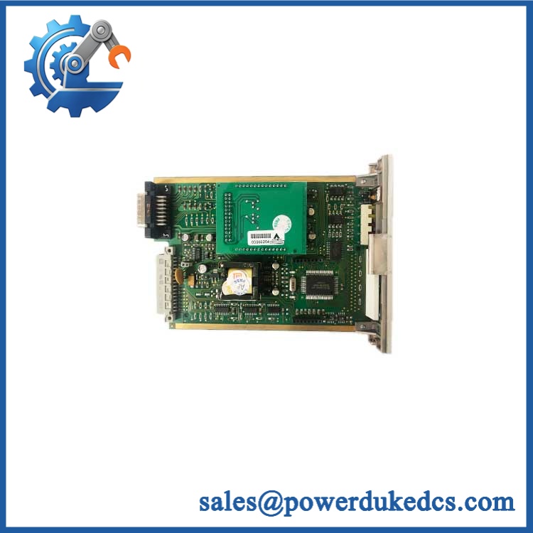
Honeywell 05701-A-0301
Module 5: Quality Assurance & Testing SOP
For a gas-detection control card, “powers up” is not an adequate release criterion. The test sequence should confirm the signal path, display functions, alarm handling and stored configuration.
- Part identity verification: Record Honeywell markings, complete 05701-A-0301 part number, serial/lot data and revision information.
- OEM anti-counterfeit visual inspection: Inspect PCB markings, component references, connectors, front-panel legends, solder quality and evidence of unauthorized repair.
- Mechanical inspection: Check the card edge, mounting hardware, connector alignment and front-panel assembly for physical damage.
- Power-input verification: Apply a controlled 18–32 VDC supply and monitor startup current and supply stability against the applicable specification.
- Power-on self-test (POST): Verify the control-card startup sequence, display operation and expected status behavior.
- 4–20 mA input simulation: Inject calibrated current points across the operating range and verify the displayed gas value tracks the reference input.
- Alarm testing: Exercise representative A1, A2 and A3 thresholds and confirm the corresponding indications and configured outputs. Honeywell documents individual, zoned, master and voted alarm functions within the System 57 architecture.
- Fault/inhibit testing: Simulate appropriate fault and inhibit conditions and verify corresponding indications.
- Reset/select function test: Verify the front-panel reset/select control operates correctly.
- EEPROM/configuration check: Confirm that the application configuration can be read and retained without checksum or memory errors.
- Sensor-drive verification: Where applicable, test the associated 05701-A-0283 4–20 mA sensor-drive function as part of the complete channel path.
- Final QC release: Record supply voltage, injected currents, displayed values, alarm states, diagnostic results, serial information and photographs; package the card in ESD protection.
Honeywell’s published specification gives less than ±2% electronic drift over six months, along with the stated 3.25 W typical power consumption and 112 × 25 × 170 mm dimensions. These values provide useful inspection baselines for incoming and pre-shipment QA.
Module 6: Procurement & Lifecycle FAQ
1. Is Honeywell 05701-A-0301 genuinely in stock, and what is the emergency-shipping cutoff?
Honeywell currently lists 05701-A-0301 in its System 57 spare-parts catalog as a “SYS57 CONTROL CARD 4-20MA INPUT.” That establishes current catalog recognition, but not the physical quantity held by any particular supplier. For an emergency order, require confirmation of the exact part number, physical quantity, condition, photographs and carrier cutoff before releasing the PO.
2. How do you guarantee the condition and authenticity of an obsolete or surplus 05701-A-0301?
The acceptance package should include exact-part-number verification, serial/lot traceability, PCB and connector inspection, controlled power-up, calibrated 4–20 mA simulation, alarm testing and EEPROM/configuration checks. A card that passes only a visual inspection should not be treated as ready for critical gas-detection service.
3. Are there firmware compatibility issues engineers should check before issuing the PO?
Yes, although the more important issue for this part is control-card software/configuration and detector-interface compatibility. Honeywell documents multiple 5701 control-card software generations and states that existing card hardware/software versions are backward compatible with newer cards. Even so, verify the installed System 57 configuration and detector type before approving a revision change.
4. Is 05701-A-0301 a single-channel card or a multi-channel module?
It is a single-channel 4–20 mA control card. Honeywell’s System 57 documentation explicitly lists it as the “Single Channel Control Card 4–20mA,” while the related 05701-A-0302 is the catalytic version.
5. What warranty and return terms should procurement require?
The PO should specify the exact 05701-A-0301 part number, accepted condition, functional-test scope, warranty duration, DOA definition, return window and required failure evidence. For this application, acceptance should include successful 4–20 mA signal simulation and alarm-function verification, not cosmetic inspection alone.











 Start Chat


